Rapid deburring device for new energy automobile motor shell machining

A technology for new energy vehicles and motor casings, which is applied in electromechanical devices, grinding drive devices, metal processing equipment, etc., and can solve the problems such as the need to improve the burr removal ability of the heat sink of the motor casing, and the gaps in the heat sink, so as to save installation time , Guaranteed accuracy and improved reliability

Inactive Publication Date: 2021-07-02
孙雪峰
View PDF1 Cites 4 Cited by
  • Summary
  • Abstract
  • Description
  • Claims
  • Application Information

AI Technical Summary

Problems solved by technology

The deburring device for motor shell production in the above-mentioned patent has the following disadvantages: although it can meet certain usage requirements, due to the small number of gaps between the heat sinks, the device’s ability to remove burrs from the heat sink of the motor shell remains to be seen. Improve

Method used


Image

  • Rapid deburring device for new energy automobile motor shell machining
  • Rapid deburring device for new energy automobile motor shell machining
  • Rapid deburring device for new energy automobile motor shell machining

Examples


Embodiment 1

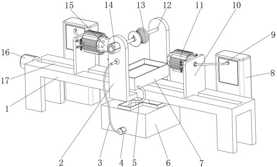
[0034] A fast deburring device for new energy vehicle motor shell processing, such as Figure 1-6As shown, it includes a workbench 1, the outer wall of the top of the workbench 1 is provided with a translation chute 17, and the outer wall of one side of the workbench 1 is fixed with a translation motor 16 by screws, and the output end of the translation motor 16 is rotationally connected through a coupling. There is a translation screw 34; the inner wall of the translation chute 17 is slidably connected with two mounting plates 10, and the mounting plates 10 are all connected to the outer wall of the translation screw 34 by threads, and the outer wall of the adjacent side of the two mounting plates 10 is fixed by screws for installation. The installation head 15 of the motor casing 11, the outer wall of the installation head 15 is embedded with an annular air bag 25, and one side of the workbench 1 is provided with an air pressure generating device 8, and the annular air bag 25...

Embodiment 2

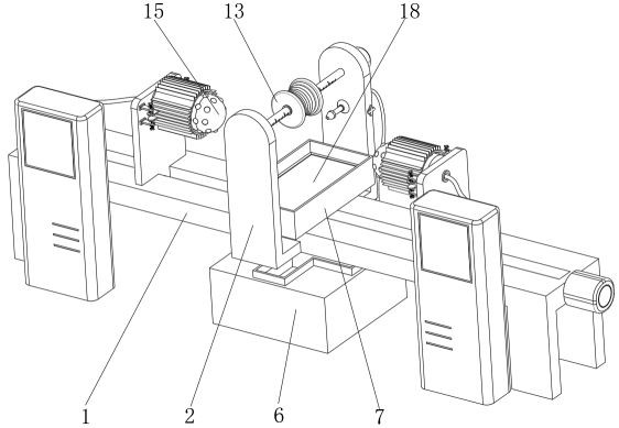
[0045] A fast deburring device for new energy vehicle motor casing processing, such as figure 1 As shown, in order to avoid the coolant pollution caused by the debris under grinding and the blockage of the nozzle 28; this embodiment makes the following improvements on the basis of embodiment 1: the inner wall of the receiving box 7 is integrally provided with two clamping ribs 36. A sponge filter plate 18 is clamped between the two clamping ribs 36; many tests have shown that by setting the sponge filter plate 18, the burrs and debris mixed in the cooling liquid can be reliably filtered, avoiding the cooling liquid Contamination leads to clogging of the nozzle 28 and the like.


PUM


Abstract

The invention discloses a rapid deburring device for new energy automobile motor shell machining, and relates to the technical field of deburring devices for motor shell machining. The processing efficiency is improved. The rapid deburring device specifically comprises a workbench, a translation sliding groove is formed in the outer wall of the top of the workbench, a translation motor is arranged on the outer wall of one side of the workbench, the output end of the translation motor is rotatably connected with a translation screw through a coupler, the inner wall of the translation sliding groove is slidably connected with two mounting plates, and the mounting plates are connected to the outer wall of the translation screw through threads. By arranging a mounting head, an annular air bag and other structures, a motor shell can be mounted on the mounting head, and an air pressure generating device is controlled to work to inflate the annular air bag, so that the annular air bag is expanded to reliably support the motor shell, and mounting is rapid and convenient; and by arranging a grinding piece assembly, the translation motor and other structures, the translation motor can be controlled to drive the mounting head on the mounting plate to move, so that grinding is realized under the rotation of the grinding piece assembly.

Description

technical field [0001] The invention relates to the technical field of processing and deburring devices for motor casings, in particular to a fast deburring device for processing motor casings of new energy vehicles. Background technique [0002] In the processing of the motor shell of new energy vehicles, in order to ensure the good heat dissipation capability of the motor, multiple protruding heat sinks are often processed on the motor shell to increase the contact area with the air, thereby enhancing the heat dissipation effect, and these motor shells dissipate heat In the process of chip processing, there are often more or less burrs. In order to control the product quality, these burrs need to be removed; the current rapid deburring device for motor shell processing can meet certain usage requirements. However, due to the small number of gaps between the heat sinks, the general grinding efficiency is slow, and the alignment is relatively difficult, so there is still roo...

Claims


Application Information

Patent Timeline
Patent Type & Authority Applications(China)
IPC IPC(8): B24B9/00B24B41/06B24B55/03B24B47/12B24B27/02H02K15/14B01D29/01B01D29/05B01D35/02
CPCB01D29/01B01D29/05B01D35/02B24B9/00B24B27/02B24B41/06B24B47/12B24B55/03H02K15/14
Inventor 孙雪峰刘伟
Owner 孙雪峰
Why Eureka
Try Eureka