
Power redundancy control system and method of GPU server and medium

A GPU server and redundant control technology, applied in the field of GPU server power redundant control system, can solve problems such as server downtime and inability to limit the power consumption of the whole machine, so as to ensure the ability to process business, reduce losses, and improve business processing The effect of the ability

Pending Publication Date: 2021-07-02
SHANDONG YINGXIN COMP TECH CO LTD
View PDF9 Cites 1 Cited by
  • Summary
  • Abstract
  • Description
  • Claims
  • Application Information

AI Technical Summary

Problems solved by technology

[0004] The main solution of the present invention is that when the BMC is abnormal or restarted, the BMC cannot limit the power consumption of the whole machine. If the server is processing business and running at full load at this time, the BMC cannot limit the power consumption of the whole machine in time, which will lead to Server down issue

Method used


Image

  • Power redundancy control system and method of GPU server and medium
  • Power redundancy control system and method of GPU server and medium
  • Power redundancy control system and method of GPU server and medium

Examples


Embodiment 1

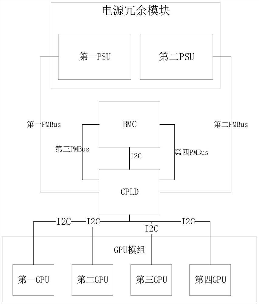
[0073] An embodiment of the present invention provides a GPU server power redundancy control system, such as figure 1 As shown, including: power redundancy module, BMC, CPLD and GPU module;

[0074] Several PSUs are arranged in the redundant power supply module;

[0075] the number of PSUs includes a first PSU and a second PSU;

[0076] The first PSU and the second PSU are connected in parallel with the same specifications, that is, when one PSU fails, the other PSU can still support the server to avoid server downtime;

[0077] Several said PSUs are respectively connected with said CPLD through several different PMBus;

[0078] Specifically, the first PSU is connected to the CPLD through the first PMBus; the second PSU is connected to the CPLD through the second PMBus;

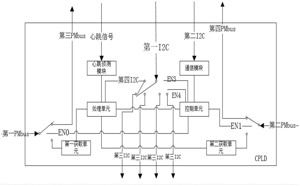
[0079] The BMC is connected to the CPLD through the first I2C bus and the second I2C bus, sends the heartbeat signal of the BMC to the CPLD, and obtains the pre-tested GPU module unloaded in the register s...

Embodiment 2

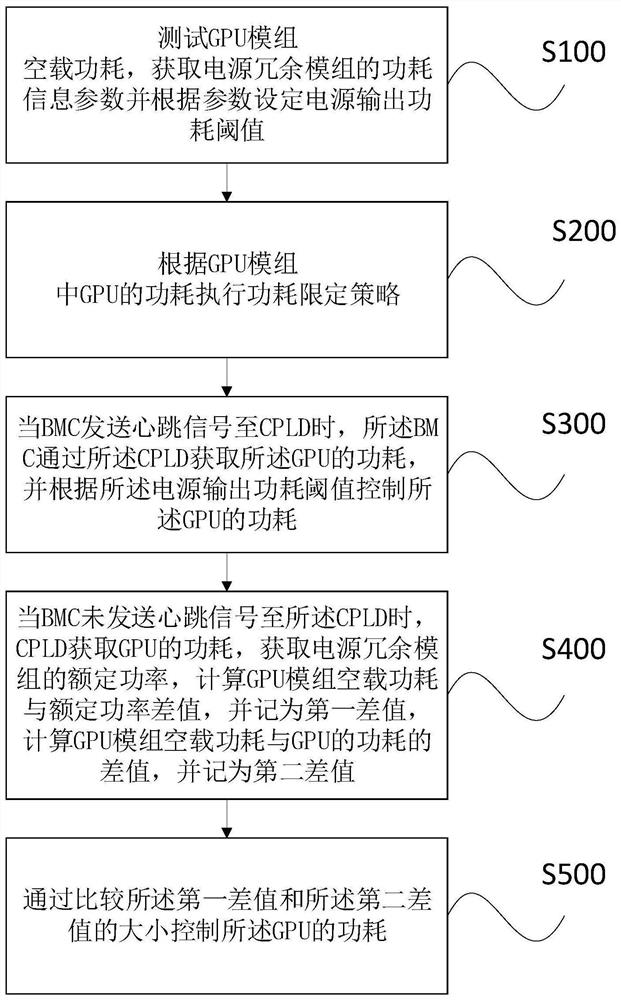
[0118] Embodiments of the present invention also provide a power redundancy control method for a GPU server, such as image 3 shown, including the following steps:

[0119] S100, when the system is running normally after startup, test the power consumption of the GPU module under no-load and store it in the register of the CPLD, the BMC obtains the power consumption information parameters of the first PSU and the second PSU through the PMbus bus, and the BMC obtains the power consumption information parameters according to the acquired Parameters to set the GPU module power output power consumption threshold;

[0120] S200, execute the power consumption limiting strategy according to the power consumption of the GPU in the GPU module; judge whether the BMC is abnormal or restarted according to the heartbeat signal;

[0121] S300, when the BMC outputs the heartbeat signal to the CPLD, the BMC is running normally, and the BMC obtains the power consumption information of each GP...


PUM


Abstract

The invention discloses a power redundancy control system of a GPU server. The power redundancy control system comprises a power redundancy module, a BMC, a CPLD and a GPU module; the power supply redundancy module comprises a first PSU and a second PSU, and the GPU module comprises a plurality of GPUs; the first PSU is connected with the CPLD through a first bus; the second PSU is connected with the CPLD through a second bus; the BMC is connected with the CPLD through the first I2C bus and the second I2C bus and sends heartbeat information to the CPLD; the CPLD is connected with the BMC through a third bus and a fourth bus; the CPLD is connected with the plurality of GPUs through a third I2C bus. According to the invention, when the BMC is abnormal or restarted, the CPLD can control the overall power consumption of the server, and meanwhile, the server can be ensured not to have a downtime phenomenon, so that the loss caused by the abnormal or restarted BMC to a client is reduced.

Description

technical field [0001] The invention relates to the field of power consumption control, in particular to a GPU server power redundancy control system, method and medium. Background technique [0002] With the rapid development of the Internet industry, more and more Internet manufacturers use GPU servers in large quantities. This kind of server is characterized by providing super computing power and can be applied to scenarios such as computing processing of massive data and deep learning training. As the computing power of the server increases, the power consumption of the whole machine will increase. GPU servers generally need high-power PSUs to meet the power consumption of the whole machine. [0003] Generally, when the GPU server is under full load, its overall power consumption is greater than the rated overall power consumption that the PSU can provide. Generally, the server will limit the power consumption of the whole machine through the power capping technology. W...

Claims


Application Information

Patent Timeline
IPC IPC(8): G06F1/30G06F1/3206G06F1/3287G06F11/20
CPCG06F1/30G06F1/3206G06F1/3287G06F11/2015Y02D10/00G06F13/4282G06F1/28G06F1/3253G06F2213/0016
Inventor 张悦韩红瑞王素华刘毓
Owner SHANDONG YINGXIN COMP TECH CO LTD
Learn More