Myocardial patch with microneedle

A myocardial patch technology, applied in the field of myocardial patch

Pending Publication Date: 2021-07-06
NINGBO DIOCHANGE MEDICAL TECH CO LTD
View PDF2 Cites 5 Cited by
  • Summary
  • Abstract
  • Description
  • Claims
  • Application Information

AI Technical Summary

Problems solved by technology

[0010] The purpose of the present invention is to overcome the deficiencies of the prior art, and provide a myocardial patch with microneedles for patients with heart failure who need interventional therapy. or the technical problems caused by the two methods of bonding, so that the myocardial patch can be quickly and effectively fixed on the target tissue without minimal trauma

Method used


Image

  • Myocardial patch with microneedle
  • Myocardial patch with microneedle
  • Myocardial patch with microneedle

Examples


specific Embodiment 1

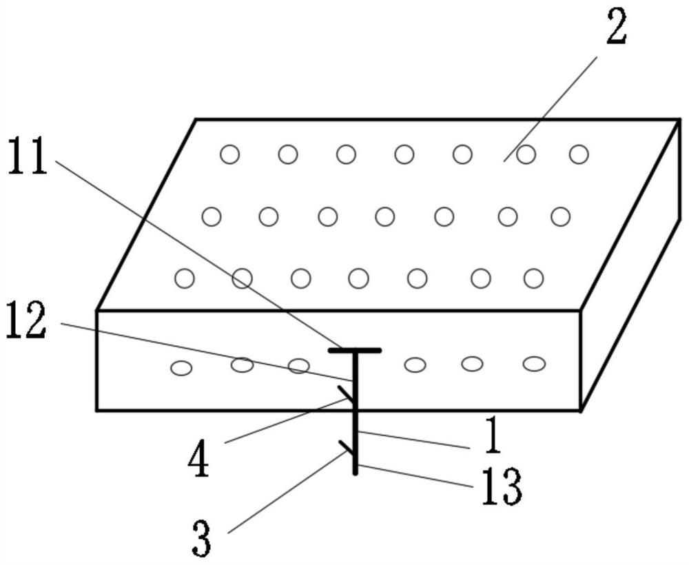
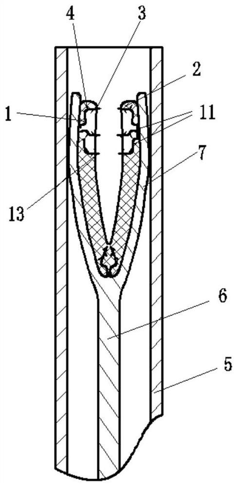
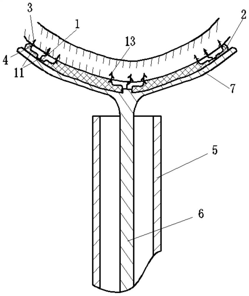
[0099] A myocardial patch 2 with a microneedle 1, comprising a myocardial patch 2 and a microneedle 1, the myocardial patch 2 has a porous structure, the myocardial patch 2 has anatomical adaptability, and the microneedle 1 From the proximal end to the distal end, it includes a needle base 11 , a needle body 12 and a needle tip 13 in sequence, wherein the needle body 12 is located between the needle base 11 and the needle tip 13 . The distal end of the needle root 11 is provided with a blocking structure 4 , and the needle body 11 and / or the needle tip 13 is provided with an anchoring structure 3 . When the myocardial patch 2 contacts the target tissue of the heart, part of the needle body 12 and the anchoring structure 3 on the microneedle 1 penetrate into the target tissue together with the needle tip 13 . The myocardial patch 2 cooperates with the blocking structure 4 and the anchoring structure 3 to achieve seamless fit and relative fixation between the myocardial patch 2 ...

specific Embodiment 2

[0121] The difference from Example 1 is:

[0122] In this embodiment, the microneedle 1 is composed of two or more identical small microneedles, and each of the small microneedles is connected as a whole through the needle root 11 at the proximal end. This embodiment has the following advantages: By increasing the number of the microneedles 1, the fixation range of the myocardial patch 2 and the anchoring force to the heart tissue are increased.

[0123] In this embodiment, the microneedle 1 is integrally formed by shape memory material through 3D printing.

[0124] In this embodiment, the needle root 11 diverges outward from the center and has a three-dimensional "bowl-shaped" structure, such as Figure 6 As shown, the spacing of each of the small microneedles on the needle root is the same and parallel to each other, and they all form a certain angle with the needle root. This design has the following advantages: 1) the preparation process is simple; 2) the use of The inte...

specific Embodiment 3

[0131] The difference from Example 1 is:

[0132] In this embodiment, the base 11 of the microneedle 1 is combined with the needle body 12 and the needle tip 13 instead of being integrated, and the needle body 12 and the needle tip 13 are of an integrated structure.

[0133] In this embodiment, the needle base 11 is provided with one or more blocking structures 4, wherein the blocking structures 4 can be holes for defining the needle body 12 and the needle tip 13 on the needle base 11. In the relative position above, the needle root diverges from the center outward to form a "fan leaf" structure, and one or more blocking structures 4 are arranged on the needle root 11 . Wherein, the blocking structure 4 is a hole, which is used to limit the relative positions of the needle body 12 and the needle point 13 on the needle base 11, such as Figure 10 shown. This design makes: 1) the length of the needle body 12 and the needle point 13 can be flexibly adjusted; 2) by reasonably se...


PUM


Abstract

The invention provides a myocardial patch with a microneedle. The myocardial patch comprises a myocardial patch body and the microneedle; the myocardial patch body is of a porous structure; the myocardial patch body has anatomical morphology adaptability; the microneedle sequentially comprises a needle root, a needle body and a needle tip from the near end to the far end, wherein the needle body is located between the needle root and the needle tip; the needle root is provided with a stop structure; an anchoring structure is arranged on the needle body and / or the needle tip; when the myocardial patch makes contact with target tissue of a heart, part or all of the needle body and the anchoring structure on the microneedle pierce into the target tissue along with the needle tip to implement minimally invasive or damage-free anchoring; the myocardial patch body, the stop structure and the anchoring structure cooperate with each other, so that the myocardial patch body and the target tissue are attached and relatively fixed; and the myocardial patch body can be implanted into a target position through a blood vessel or an endoscope by means of a delivery system, thus implementing a minimally invasive implantation operation.

Description

technical field [0001] The invention belongs to the field of medical devices, in particular to a myocardial patch with microneedles. Background technique [0002] Heart failure, referred to as heart failure, is the terminal stage of heart disease development, and the vast majority of heart failure begins with left heart failure. At present, the number of deaths caused by chronic heart failure and myocardial infarction is gradually increasing. The main treatment methods for heart failure are: cardiac assist device, drug therapy and end-stage heart transplantation. For early research cardiac assist devices, such as Acorn CorCap, the double ventricle coating method was used for mechanical enhancement, but this type of device is large in size, and excessive contact with normal myocardium will cause harmful effects on normal myocardium, and drugs Like treatment, the process of developing heart failure cannot be fundamentally reversed. In addition, heart transplantation is diffi...

Claims


Application Information

Patent Timeline
Patent Type & Authority Applications(China)
IPC IPC(8): A61F2/00
CPCA61F2/0063
Inventor 李彪吕世文陈超董娟胡晓明
Owner NINGBO DIOCHANGE MEDICAL TECH CO LTD
Why Eureka
Try Eureka