
Multi-feed stirring equipment for animal husbandry

A feed mixing and animal husbandry technology, applied in feed, mixer accessories, mixers with rotary mixing devices, etc., can solve the problems of time-consuming, manual manual loading and unloading, and unbalanced livestock nutrition.

Pending Publication Date: 2021-07-06
张引
View PDF7 Cites 4 Cited by
  • Summary
  • Abstract
  • Description
  • Claims
  • Application Information

AI Technical Summary

Problems solved by technology

[0002] The existing mixing method is mainly to pour a variety of feeds into the device together, and then stir the feeds with hands or tools. This method is repetitive physical labor, time-consuming, and uneven mixing will cause nutritional imbalances for livestock. state, which is detrimental to the health of livestock
[0003] Patent application: CN209005598U, the publication date is 20190621, which discloses a feed mixing equipment for animal husbandry, through which the rotating disk is rotated clockwise and the threaded rod is rotated inside the threaded hole, and then the bottom end of the threaded rod is fixed in the groove It is convenient for the U-shaped fixing plate to be installed and fixed on the upper surface of the sealing cover, and to increase the sealing effect of the connection between the sealing cover and the main body of the feed mixing equipment, and it is convenient for the U-shaped fixing plate to be turned down from the upper surface of the sealing cover and lifted by the handle. Take off the sealing cover, the device is easy to operate and simple in structure, but the device only achieves the function of stirring, and manual loading and unloading is required, which consumes manpower

Method used


Image

  • Multi-feed stirring equipment for animal husbandry
  • Multi-feed stirring equipment for animal husbandry
  • Multi-feed stirring equipment for animal husbandry

Examples


Embodiment 1

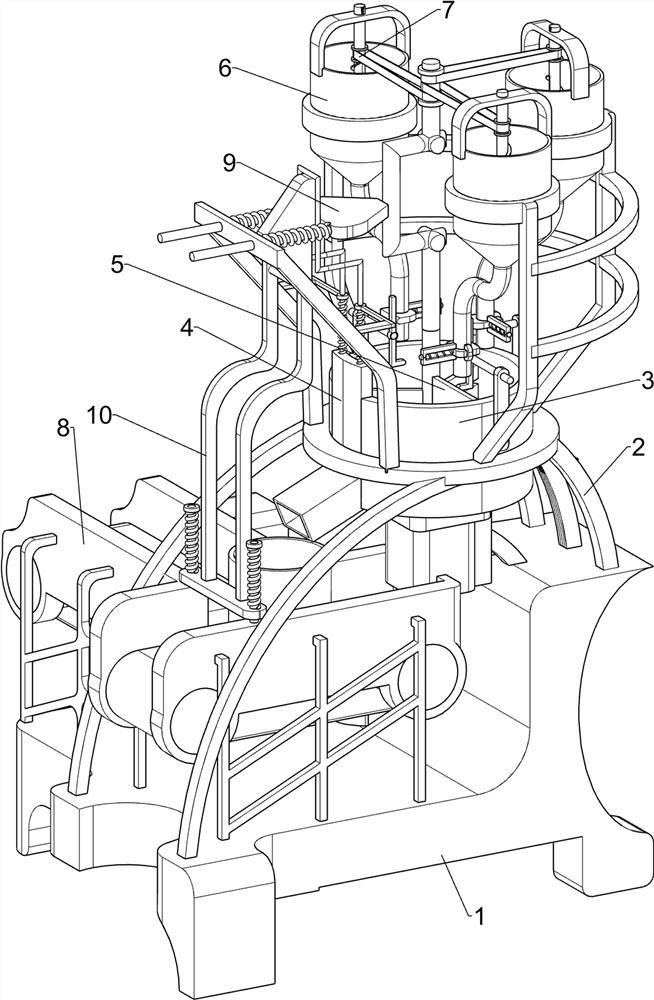
[0073] A variety of feed mixing equipment for animal husbandry, such as figure 1 As shown, it includes base plate 1, support 2, mixing barrel 3, baffle plate 4, stirring mechanism 5 and interval blanking mechanism 6, base plate 1 upper front side is provided with support 2, and support 2 is provided with stirring barrel 3, and stirring barrel 3 The left sliding type is provided with a baffle plate 4, a stirring mechanism 5 is provided between the bottom plate 1 and the mixing bucket 3, and an interval feeding mechanism 6 is provided between the bracket 2 and the mixing bucket 3.

[0074] When people need to stir the feed, they can use this variety of feed mixing equipment for animal husbandry. People put three different types of feed in the interval feeding mechanism 6, then start the stirring mechanism 5, and the movement of the stirring mechanism 5 drives The feeding mechanism 6 moves at intervals, so that the three feeds fall into the mixing tank 3, and the stirring mechani...

Embodiment 2

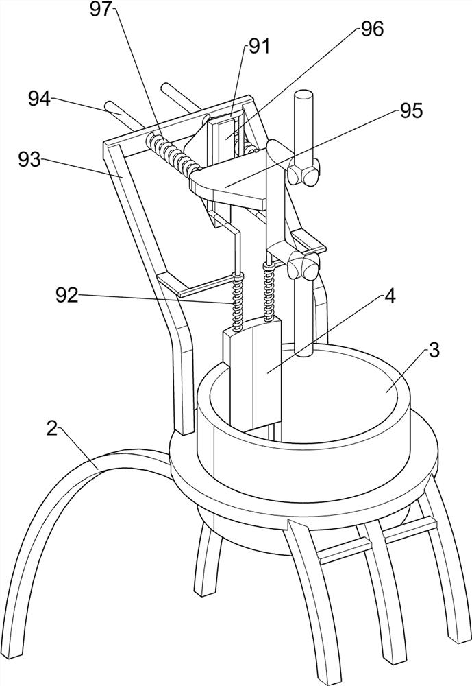
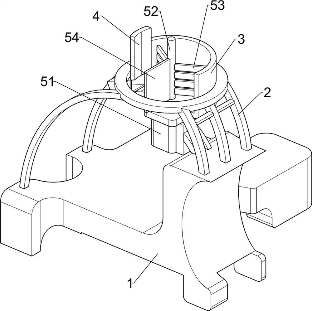
[0076] On the basis of Example 1, such as figure 2 and image 3 As shown, the stirring mechanism 5 includes a first servo motor 51, a first rotating shaft 52, a stirring plate 53 and a scraper 54. The first servo motor 51 is installed on the right side of the upper front part of the bottom plate 1, and the rotary device on the mixing bucket 3 There is a first rotating shaft 52, which is connected with the output shaft of the first servo motor 51, the left and right sides of the first rotating shaft 52 are provided with stirring plates 53, and the front side of the first rotating shaft 52 is provided with a scraper 54.

[0077] When the three different types of feed are placed in the interval feeding mechanism 6, people start the first servo motor 51, and the output shaft of the first servo motor 51 rotates to drive the first rotating shaft 52 to rotate, thereby driving the stirring plate 53 and the scraper 54 rotates, and the scraper 54 rotates to drive the 6 parts of the in...

Embodiment 3

[0081] On the basis of Example 2, such as Figure 4-7 As shown, anti-clogging mechanism 7 is also included, and anti-clogging mechanism 7 includes special-shaped rod 71, the third fixed block 72, threaded rotating shaft 73 and transmission belt 74, is connected with special-shaped rod 71 on the first rotating shaft 52, storage barrel 62 The third fixed block 72 is connected on the top, and the third fixed block 72 is rotatably connected with a threaded rotating shaft 73. Between the threaded rotating shaft 73 and the special-shaped rod 71, there are three transmission belts 74.

[0082] The first rotating shaft 52 rotates and drives the special-shaped bar 71 to rotate, thereby making the transmission belt 74 rotate, and then the threaded rotating shaft 73 rotates, and then the feed in the storage barrel 62 is stirred, preventing the feed from blocking the feed pipe 63.

[0083] Also include delivery mechanism 8, delivery mechanism 8 includes installation outer frame 81, second...


PUM


Abstract

The invention relates to stirring equipment, in particular to multi-feed stirring equipment for animal husbandry. The invention provides the multi-feed stirring equipment for animal husbandry, which has the advantages of automatic feeding and automatic stirring and is simple and convenient. The multi-feed stirring equipment for animal husbandry comprises a bottom plate, a support, a stirring barrel, a baffle, a stirring mechanism and an interval discharging mechanism; and the support is arranged on the bottom plate; the stirring barrel is arranged on the support; the baffle is arranged on the stirring barrel in a sliding manner; the stirring mechanism is arranged between the bottom plate and the stirring barrel; and the interval discharging mechanism is arranged between the support and the stirring barrel. A first servo motor is started, an output shaft of the first servo motor rotates to drive a first rotating shaft to rotate, so that a stirring plate and a scraping plate are driven to rotate, and when feed falls into a stirring barrel, the stirring effect is achieved.

Description

technical field [0001] The invention relates to a stirring device, in particular to a stirring device for various feeds used in animal husbandry. Background technique [0002] The existing mixing method is mainly to pour a variety of feeds into the device together, and then stir the feeds with hands or tools. This method is repetitive physical labor, time-consuming, and uneven mixing will cause nutritional imbalances for livestock. The state is not conducive to the health of livestock. [0003] Patent application: CN209005598U, the publication date is 20190621, which discloses a feed mixing equipment for animal husbandry, through which the rotating disk is rotated clockwise and the threaded rod is rotated inside the threaded hole, and then the bottom end of the threaded rod is fixed in the groove It is convenient for the U-shaped fixing plate to be installed and fixed on the upper surface of the sealing cover, and to increase the sealing effect of the connection between the...

Claims


Application Information

Patent Timeline
IPC IPC(8): B01F7/16B01F7/18B01F15/02A23N17/00
CPCA23N17/007B01F27/808B01F27/90B01F35/71715B01F35/7173B01F35/7541B01F35/71B01F2101/18
Inventor 张引
Owner 张引
Learn More