
Automatic welding method for steel beam rod part groove-shaped structure

An automatic welding and groove technology, applied in welding equipment, welding accessories, arc welding equipment, etc., can solve the problems of narrow internal space, low efficiency, large welding volume, etc.

Active Publication Date: 2021-07-06
中铁宝桥(扬州)有限公司 +1
View PDF6 Cites 3 Cited by
  • Summary
  • Abstract
  • Description
  • Claims
  • Application Information

AI Technical Summary

Problems solved by technology

[0004] Due to the complexity of the internal structure, the welding of steel truss bridge bar grooves has remained at the level of manual welding in the industry. The internal space of the grooves is narrow and the welding volume is large, the welding working conditions are poor and the efficiency is low, and the welding quality is not good. Stablize

Method used


Image

  • Automatic welding method for steel beam rod part groove-shaped structure
  • Automatic welding method for steel beam rod part groove-shaped structure
  • Automatic welding method for steel beam rod part groove-shaped structure

Examples


Embodiment Construction

[0036] The present invention will be described in further detail below in conjunction with specific examples, but the embodiments of the present invention are not limited thereto.

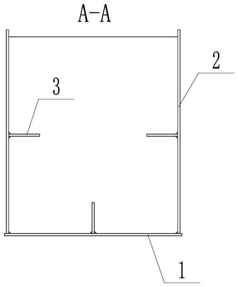
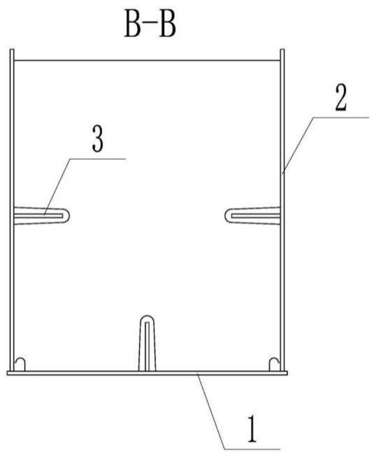
[0037] See also Figure 1 to Figure 10 , the present invention provides an automatic welding method for the groove structure of a steel beam member. The grooved member is assembled from a bottom plate, a web, a middle partition, an end partition, and a stiffener. The automatic welding process includes The following steps:

[0038] S1: Assembly of steel girder trough members: weld the stiffeners to the web and bottom plate respectively to form the web unit and the bottom plate unit; where the stiffener includes the web stiffener and the bottom plate stiffener; The plate, web unit, and bottom plate unit are assembled into grooves and completed positioning welding. The assembly gap is 1mm and the verticality is 0.5mm.

[0039] Among them, there are welding holes between the middle diaphragm and the ...


PUM

PropertyMeasurementUnit
angleaaaaaaaaaa
verticalityaaaaaaaaaa

Abstract

The invention discloses an automatic welding method for a steel beam rod part groove-shaped structure. The automatic welding method comprises the following steps that 1, transverse partition plates, a web plate, a bottom plate and stiffening ribs are assembled; 2, during welding, an arcing point is located at the bottom of a vertical welding seam of a middle partition plate and the web plate; 3, vertical fillet welds of the middle partition plate and the web plate are welded; 4, flat angle fillet welds of the middle partition plates and the bottom plate, and flat angle fillet weld of the web plate and the bottom plate are welded; 5, the previous step is repeated until all the middle partition plates are welded; 6, end partition plates are welded, and after arcing, vertical position fillet welds of the end partition plates at the lower sides of the web plate stiffening ribs and the web plate, elevation angle position and flat angle position fillet welds of the end partition plates and the web plate stiffening ribs, and vertical position fillet welds of the end partition plates at the upper sides of the web plate stiffening ribs and web plate are welded; 7, welding flat angle fillet welds of the web plate and the bottom plate, flat angle fillet welds of the end partition plates and the bottom plate and vertical fillet welds of the end partition plates and the bottom plate stiffening ribs are welded; and 8, the previous step is repeated until all the end partition plates are welded to other panels. The method can be used for welding a groove-shaped portion of a rod part, and the welding seam quality can be greatly improved.

Description

technical field [0001] The invention belongs to the bridge manufacturing industry, and in particular relates to an automatic welding method for a groove structure of a steel beam member. Background technique [0002] Steel trusses are mainly composed of main truss members (upper and lower chords, diagonal members and vertical members), bridge deck tie members (longitudinal and horizontal beams), connecting tie members (parallel link members, horizontal link members and bridge door members) ) and other components, in which the upper and lower chords, inclined bars and vertical bars are mostly single-chamber structures. During manufacture, they are first assembled into grooves, and the internal welds are welded. Finally, the cover is buckled and other parts are assembled and welded. [0003] Steel truss bridge member grooves are generally composed of bottom plates, webs, stiffeners, and transverse diaphragms. The transverse diaphragms include middle diaphragms and end diaphrag...

Claims


Application Information

Patent Timeline
Patent Type & Authority Applications(China)
IPC IPC(8): B23K9/00B23K9/09B23K9/16B23K9/235B23K9/32
CPCB23K9/0026B23K9/235B23K9/16B23K9/09B23K9/32
Inventor 薛喆彦吴江波袁俊刘志刚杜伟
Owner 中铁宝桥(扬州)有限公司
Learn More