Oscillatory scanning laser beam-electric arc hybrid welding method and system

A technology of hybrid welding and laser beam, which is applied in the field of laser beam-arc hybrid welding of metal materials and oscillation scanning laser beam-arc hybrid welding, which can solve the problem that the welding requirements of light alloy structures cannot be met and the implementation of laser beam scanning movement is difficult , single laser beam scanning path, etc., to achieve excellent technical capabilities, improve welding characteristics and welding quality, and reduce welding spatter

Active Publication Date: 2015-04-15
武汉飞能达激光技术有限公司
View PDF4 Cites 7 Cited by
  • Summary
  • Abstract
  • Description
  • Claims
  • Application Information

AI Technical Summary

Problems solved by technology

The problem is that it is difficult to implement the laser beam scanning movement driven by robots or other mechanical means, not only the response time is slow, the vibration frequency is too low, the stability is poor, the laser beam scanning path is single, and the structure of the process is complicated, so the Technology research and application are very limited
Laser galvanometer scanning welding can refine the weld grains, reduce the tendency of cracks, and improve the strength of the joint through the oscillation scanning of the laser beam, but because the laser welding molten pool is too narrow, the solidification speed is too fast, and the laser pinhole is unstable, The ability of this process to suppress porosity is relatively limited, and the tendency of weld porosity is still very large, which cannot meet the welding needs of aluminum alloy, magnesium alloy, titanium alloy and other light alloy structures.

Method used


Image

  • Oscillatory scanning laser beam-electric arc hybrid welding method and system
  • Oscillatory scanning laser beam-electric arc hybrid welding method and system
  • Oscillatory scanning laser beam-electric arc hybrid welding method and system

Examples


Embodiment 1

[0040] The workpiece material is 6082-T6 deformed aluminum alloy with a thickness of 8mm, and the welding method is flat welding.

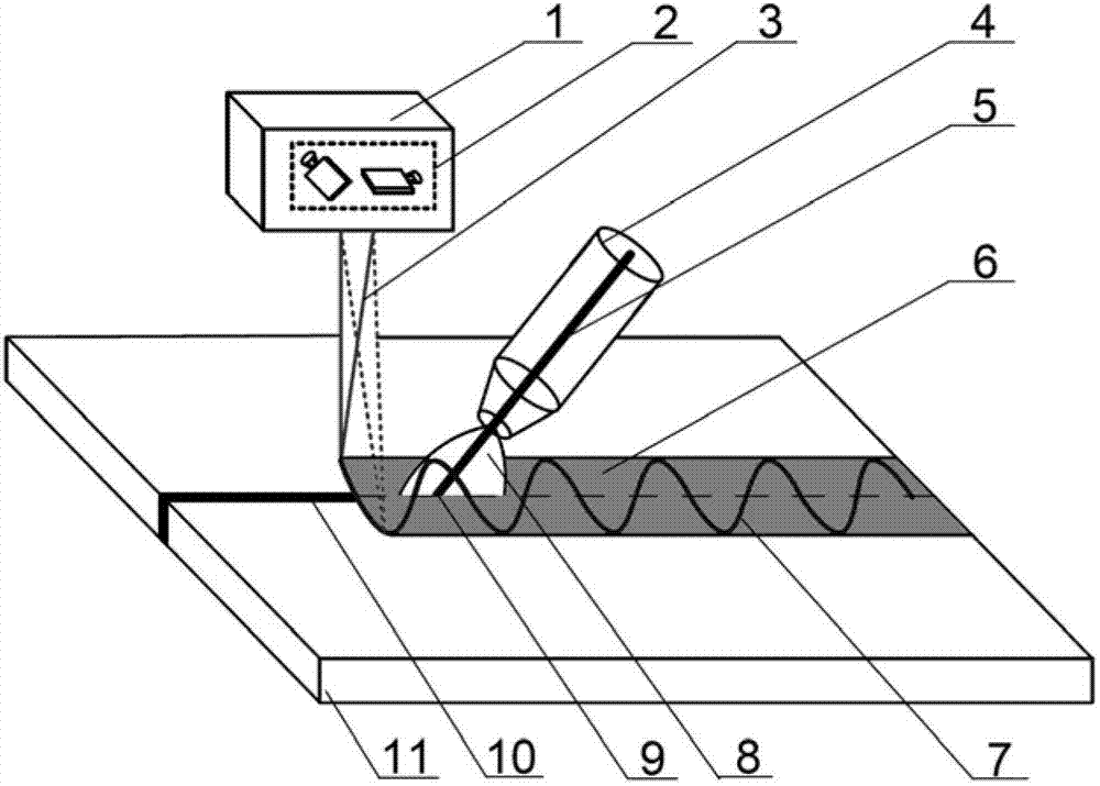
[0041] In this embodiment, the operating platform is a six-axis robot system, the laser light source is a 10,000W fiber laser, the arc heat source is a 500A pulse digitally controlled fusion inert gas welder, the laser beam is transmitted to the vibrating mirror through an optical fiber, and the focal length of the vibrating mirror is 300mm.

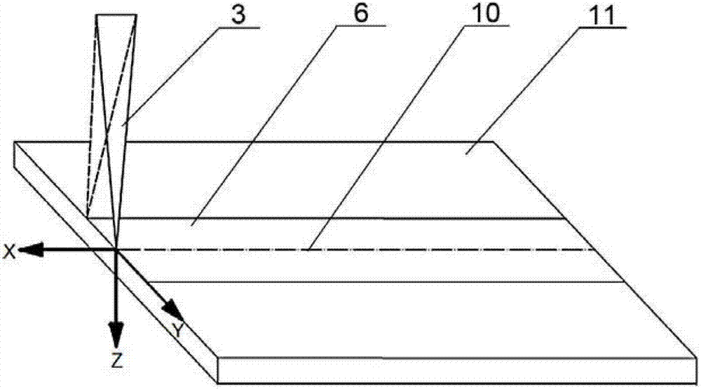
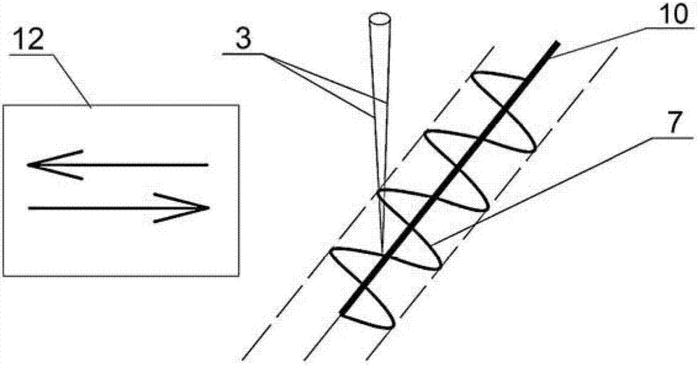
[0042] The technical parameters of the oscillating laser beam-arc hybrid welding in this embodiment are: the angle between the laser beam and the arc torch is 30°, the laser-arc distance is 4mm, the defocus of the laser beam is -2mm, the laser power is 10000W, and the arc current The welding speed is 320A, the welding speed is 6m / min; the scanning displacement range of the laser beam in the X direction is -2-3mm, the scanning displacement in the Y axis direction is -5-5mm, and the scanning displacement in the...

Embodiment 2

[0045] The workpiece material is AZ31B wrought magnesium alloy with a thickness of 2mm, and the welding method is flat welding.

[0046] In this embodiment, the operating platform is a six-axis robot system, the laser light source is a 2000W DISC laser, the arc heat source is a 200A tungsten argon arc welding machine, the laser beam is transmitted to the vibrating mirror through an optical fiber, and the focal length of the vibrating mirror is 250mm.

[0047] The technical parameters of the oscillating laser beam-arc hybrid welding in this embodiment are: the angle between the laser beam and the arc torch is 40°, the laser-arc distance is 1mm, the defocus of the laser beam is 2mm, the laser power is 500W, and the arc current is 150A, the welding speed is 2m / min, the scanning displacement of the laser beam in the X direction is -1-2mm, the scanning displacement in the Y axis direction is -3-3mm, and the scanning displacement in the Z axis direction is -1-1mm, The oscillation fr...

Embodiment 3

[0050] The workpiece material is a TC4 titanium alloy cylinder with a thickness of 5mm, and the welding method is circular seam splicing.

[0051] In this embodiment, the operating platform is a three-axis CNC machining platform, and the laser light source is an 8000W CO 2 The slab laser, the arc heat source is a 500A pulse digital control fusion inert gas welding machine, the laser beam is transmitted to the vibrating mirror through the optical transmission mirror group, and the focal length of the vibrating mirror is 400mm.

[0052] The specific process parameters of the oscillating laser beam-arc hybrid welding in this embodiment are: the angle between the laser beam and the arc welding torch is 35°, the laser-arc distance is 2.5mm, the defocus of the laser beam is 0, the laser power is 4000W, the arc The current is 200A, the welding speed is 2.5m / min, the scanning displacement of the laser beam in the X direction is -1-1mm, the scanning displacement in the Y axis direction...


PUM

PropertyMeasurementUnit
thicknessaaaaaaaaaa
tensile strengthaaaaaaaaaa
thicknessaaaaaaaaaa

Abstract

The invention discloses an oscillatory scanning laser beam-electric arc hybrid welding method and system. Laser beams and electric arc move together along an abutted seam in large range space, simultaneously the laser beams surround acting points of the electric arc to perform oscillatory scanning movement in a local small area, and an actual welding track is a curve formed by overlying two types of movements. As for an optimal range of laser beam oscillatory scanning displacement, the range in the direction of an X axis is minus 2mm to 3mm, the range in the direction of an Y axis is minus 5mm to 5mm, the range in the direction of a Z axis is minus 2mm to 2mm, and the oscillation frequency is in a range from 20Hz to 500Hz. According to the method and the system, an enhanced technical effect is achieved by the aid of interaction of a laser beam oscillatory scanning effect and a laser-electric arc synergistic effect, and the welding quality is improved. Compared with existing laser-electric arc hybrid welding and laser scanning welding methods and systems, the method and the system have the advantages that higher weld porosity inhibiting capability is achieved, and the weld strength is improved by 10% to 50%.

Description

technical field [0001] The hybrid welding technology of the present invention specifically relates to an oscillation scanning laser beam-arc hybrid welding method and system, and is especially suitable for laser beam-arc hybrid welding of metal materials. Background technique [0002] Laser-arc hybrid welding utilizes the interaction between the two heat sources of laser and arc, which has better welding characteristics, and has the advantages of large laser welding penetration, good joint quality, high efficiency, small deformation and good arc welding bridging performance. The advantages of strong adaptability to complex environments are currently one of the most eye-catching metal material connection technologies. However, the significant difference in welding characteristics between arc and laser has resulted in a series of technical difficulties that need to be overcome in terms of weld formation and joint microstructure uniformity in laser-arc hybrid welds. Specifical...

Claims


Application Information

Patent Timeline
Patent Type & Authority Patents(China)
IPC IPC(8): B23K26/348B23K26/082
Inventor 高明曾晓雁李祥友严军蒋明李耿张臣
Owner 武汉飞能达激光技术有限公司
Why Eureka
Try Eureka