Laser scanning-TIG composite melting strip welding method

A laser scanning and welding method technology, applied in laser welding equipment, welding equipment, metal processing equipment and other directions, can solve the problems of poor gap adaptability, high assembly accuracy requirements, unstable welding process, etc., to reduce assembly accuracy and enhance stirring. The effect of improving welding efficiency

Inactive Publication Date: 2019-08-09
BEIJING UNIV OF TECH
View PDF6 Cites 7 Cited by
  • Summary
  • Abstract
  • Description
  • Claims
  • Application Information

AI Technical Summary

Problems solved by technology

[0006] Aiming at the problems of laser-TIG composite filler wire welding with high assembly precision, poor gap ada

Method used


Image

  • Laser scanning-TIG composite melting strip welding method

Examples


Embodiment Construction

[0025] In order to make the purpose, technical solutions and advantages of the embodiments of the present invention clearer, the technical solutions in the embodiments of the present invention will be clearly and completely described below in conjunction with the drawings in the embodiments of the present invention. Obviously, the described embodiments It is a part of embodiments of the present invention, but not all embodiments.

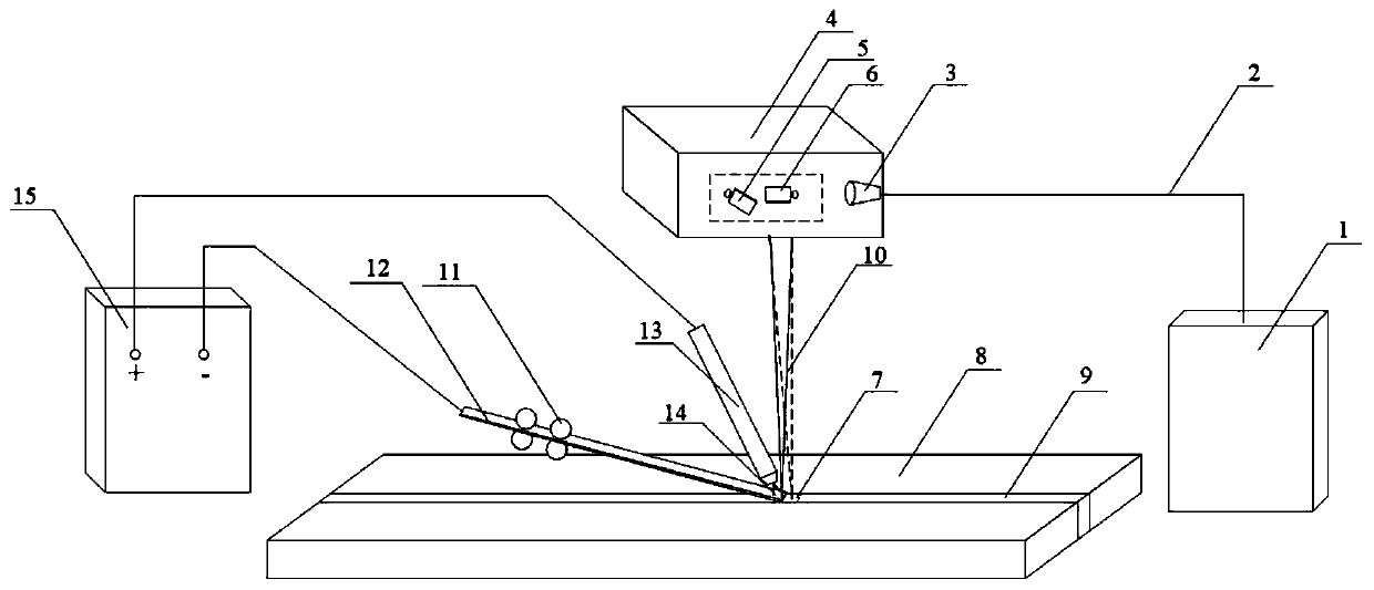
[0026] A laser scanning-TIG composite melting ribbon welding method, which is realized by laser scanning and TIG welding composite melting ribbon, is characterized in that it includes:

[0027] When welding, use a strip-shaped welding wire with a rectangular cross-section. The belt-feeding mechanism sends the strip-shaped welding wire above the gap between the workpieces to be welded. The width direction of the strip-shaped welding wire forms a certain angle with the welding direction. The ribbon welding wire is connected to the negative electrode o...


PUM

PropertyMeasurementUnit
Widthaaaaaaaaaa
Thicknessaaaaaaaaaa

Abstract

The invention discloses a laser scanning-TIG composite melting strip welding method. The laser scanning-TIG composite melting strip welding method comprises the following steps: during welding, a strip-shaped welding wire with a rectangular section is used; a strip conveying mechanism conveys the strip-shaped welding wire into the space above a gap of a workpiece to be welded; the width directionof the strip-shaped welding wire forms a certain angle with a welding direction; one end of a TIG welding gun is connected with a positive pole of an output end of a power supply; the strip-shaped welding wire is connected with a negative pole of the output end of the power supply; a laser beam scans in the welding direction; one half of a scanning area is located in the strip-shaped welding wire,and the other half is located in a molten pool; and a laser scanning path has different manners according to different materials and welding requirements. According to the laser scanning-TIG composite melting strip welding method, the mutual coupling action of laser and an electric arc is improved; the stirring action of laser on the molten pool is improved; the shortage of driving flow in the molten pool by virtue of surface tension purely is made up; the solidification time of the molten pool is prolonged; and the temperature gradients of molten drops and the molten pool and the impact of the molten drops on the molten pool are reduced, so that the escape of bubbles is benefited, and the formation of crystallization cracks is suppressed.

Description

technical field [0001] The invention belongs to the field of welding technology, in particular to a laser scanning-TIG composite melting ribbon welding method. Background technique [0002] Laser welding is a process in which a focused laser beam is used as a source of moving heat to join metal parts. The focused laser beam has a high power density, and has the characteristics of fast welding, large penetration depth, and narrow heat-affected zone. Laser welding is more and more widely used in automotive, aerospace, defense industry, shipbuilding, marine engineering and other fields. [0003] Laser-TIG arc hybrid welding, by applying an electric arc near the laser beam, thereby reducing the electron density, diluting the plasma cloud, reducing the consumption of laser energy, and significantly improving the laser absorption rate of the workpiece. Moreover, since the laser absorption rate of the workpiece increases with the increase of temperature, the arc preheats the weld...

Claims


Application Information

Patent Timeline
IPC IPC(8): B23K26/348
CPCB23K26/348
Inventor 陈树君贾亚洲肖珺黄文浩苑城玮
Owner BEIJING UNIV OF TECH
Why Eureka
Try Eureka