Air pressure adjusting method and device for ultra-high-speed elevator shaft

A technology of air pressure adjustment and elevator shaft, which is applied in the direction of transportation and packaging, elevators and elevators in buildings, etc., which can solve the problems of uncertain on-site effects, increased construction costs, and obvious differences in the effects of vents.

Active Publication Date: 2021-07-06
HITACHI ELEVATOR SHANGHAI +1
View PDF7 Cites 1 Cited by
  • Summary
  • Abstract
  • Description
  • Claims
  • Application Information

AI Technical Summary

Problems solved by technology

[0004] Problems and disadvantages of the prior art: due to the fixed area of ​​the vent, the temperature and humidity in the well vary in different seasons, resulting in obvious differences in the effect of the vent due to seasonal changes, which affects the comfort of the ride; in addition, the calculation formula of the well vent The vent area shown can only be used as a reference. Due to the influence of the building environment, the actual on-site effect is uncertain. If the ventilation area of ​​the hoistway is too small, it will affect the comfort in the car and the noise outside the hall. It will be more difficult to rectify the building body again. ; Due to the limitation of the building body, if the ventilation openings with a total area of ​​sufficient area are set according to the design requirements of the elevator manufacturer, the construction cost will be increased
However, the adjustment of the size of the vent area is passive and lagging behind the adjustment of the hoistway air pressure; the effect of reducing the noise in the car is also limited. When the opening area reaches a certain size, the opening area becomes larger, and the noise value in the car does not will continue to get smaller, and the effect of reducing car shaking will no longer increase
In addition, this invention does not solve the problem of increased construction costs caused by opening large-area vents, and the difficulty of rectification in the later stage

Method used


Image

  • Air pressure adjusting method and device for ultra-high-speed elevator shaft
  • Air pressure adjusting method and device for ultra-high-speed elevator shaft
  • Air pressure adjusting method and device for ultra-high-speed elevator shaft

Examples


Embodiment 1

[0039] Embodiment 1: This embodiment is a method for regulating air pressure in an ultra-high-speed elevator shaft.

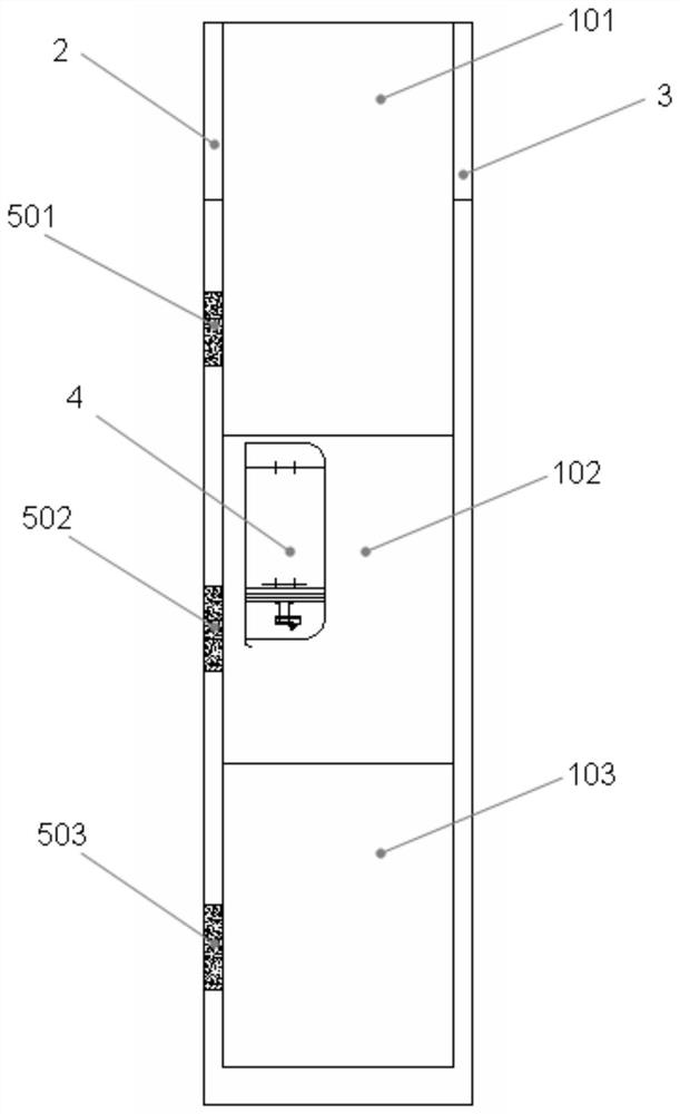
[0040] Such as figure 2 As shown, the ultra-high-speed elevator shaft includes shaft top 101, shaft middle 102, shaft bottom 103, shaft front wall 2, shaft rear wall 3, and car 4 runs up and down in the shaft. The air pressure regulation method of the ultra-high-speed elevator hoistway in this embodiment does not need to set up a large-area natural ventilation opening in the shaft, but only needs to set up the ventilation opening of the forced ventilation pressure regulating device in the shaft. The vents in this embodiment are set on the front wall of the well, wherein the vent 501 is set on the top 101 of the well, the vent 502 is set on the middle 102 of the well, and the vent 503 is set on the bottom 103 of the well, and each vent is equipped with forced ventilation. The pressure regulating device (not shown in the figure), the forced ventilation pressure...

Embodiment 2

[0050] Embodiment 2: This embodiment is another method for adjusting the air pressure in the shaft of an ultra-high-speed elevator.

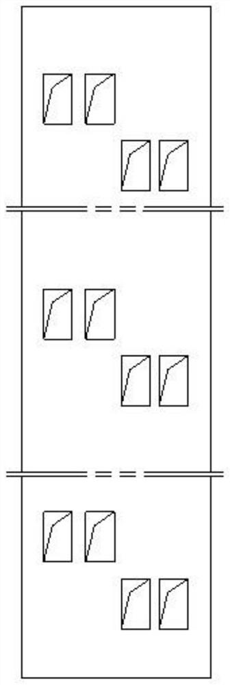
[0051] The hoistway parameters and car parameters of this embodiment are the same as those of Embodiment 1; in this embodiment, a set of forced ventilation and pressure regulating device is installed on the top of the hoistway, and the forced ventilation opening is set on the top of the hoistway, and at the same time, it is set on the side wall of the hoistway at the bottom of the hoistway. figure 1 The natural ventilation port used in the prior art shown; the forced ventilation pressure regulating device includes two axial flow fans: axial flow fan one and axial flow fan two; the airflow direction of the two axial flow fans is connected in parallel to the forced ventilation There is a damper in the duct, and the damper has two working positions: position 1 and position 2; when the damper is at position 1, only the axial flow fan 1 communicates w...

Embodiment 3

[0061] Embodiment 3: This embodiment is an air pressure regulating device for an ultra-high-speed elevator shaft.

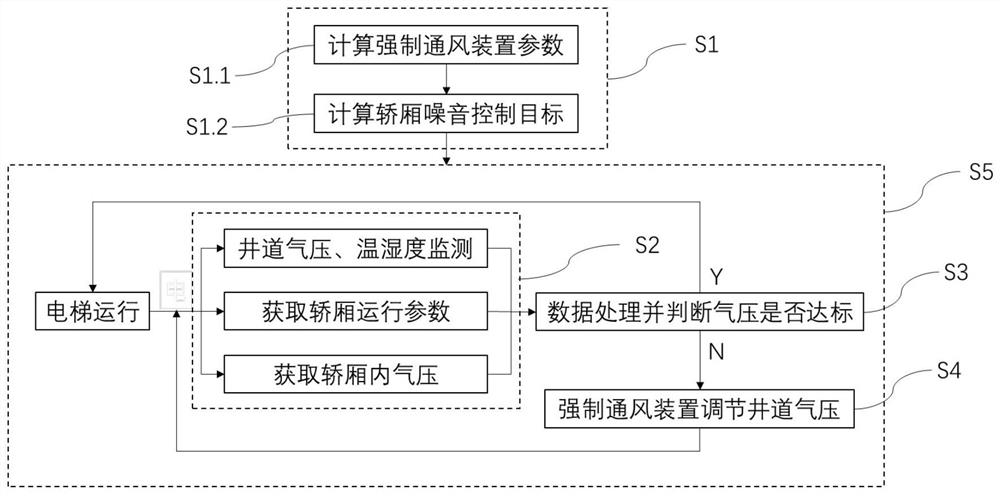
[0062] Such as figure 2 As shown, the ultra-high-speed elevator shaft includes shaft top 101, shaft middle 102, shaft bottom 103, shaft front wall 2, shaft rear wall 3, and car 4 runs up and down in the shaft. The hoistway air pressure regulating device of this embodiment includes a controller (not shown in the figure), a wellway air pressure and temperature and humidity monitoring device (not shown in the figure), a forced ventilation pressure regulating device (not shown in the figure), the wellway air pressure and The temperature and humidity monitoring device and the forced ventilation and pressure regulating device are all connected to the controller. The hoistway air pressure and temperature and humidity monitoring device monitors the well air pressure, temperature and humidity data in real time and sends them to the controller, and the controller sends t...


PUM


Abstract

The invention discloses an air pressure adjusting method for an ultrahigh-speed elevator shaft. The method utilizes a forced ventilation pressure adjusting device to adjust shaft air pressure, and comprises the following steps: calculating parameters of the forced ventilation pressure adjusting device; obtaining shaft air pressure monitoring data and elevator operation data; and calculating shaft air pressure adjusting parameters to control a flow and an airflow direction of the forced ventilation pressure adjusting device, and adjusting the shaft air pressure. The invention further discloses an air pressure adjusting device for an ultrahigh-speed elevator shaft. The device comprises a controller, a shaft air pressure monitoring device and a forced ventilation pressure adjusting device. The shaft air pressure monitoring device monitors shaft air pressure in real time and sends the shaft air pressure to the controller, and the controller calculates shaft air pressure adjusting parameters and controls the forced ventilation pressure adjusting device to achieve adjustment of the shaft air pressure by supplying air to the shaft or exhausting air from the shaft. According to the method and the device, the building tapping cost can be saved, adapting to the actual situation and seasonal change of a building can be realized, noise and air pressure of an elevator car are improved, and the phenomenon that the self-closing force of a landing door is insufficient is improved.

Description

technical field [0001] The present application relates to the field of air pressure regulation in an ultra-high-speed elevator shaft, in particular to a method and device for adjusting air pressure in an ultra-high-speed elevator shaft. Background technique [0002] At present, in the field of ultra-high-speed elevator technology, for problems such as poor car comfort caused by shaft wind pressure and insufficient self-closing force of landing doors, ventilation openings with a fixed area are used in the shaft to deal with them, such as figure 1 shown. Major elevator manufacturers will calculate the area of ​​the shaft vents according to their own calculation formulas, including the shaft plunger ratio and elevator speed. [0003] Taking an elevator manufacturer as an example, the size and position of the vent hole are briefly described as follows: When the speed is 4m / s≤ν≤6m / s, opening the vent can effectively reduce the noise in the car and improve ride comfort; the best ...

Claims


Application Information

Patent Timeline
IPC IPC(8): B66B11/00B66B5/00B66B11/02
CPCB66B11/00B66B5/00B66B11/028
Inventor 吴林志
Owner HITACHI ELEVATOR SHANGHAI
Why Eureka
Try Eureka