
Pneumatic driving type power mechanism

A power mechanism and air pressure drive technology, which is applied in fluid pressure actuation devices, mechanical equipment, transmission devices, etc., can solve problems such as large limitations, low power, and inability to realize power rotation output

Pending Publication Date: 2021-07-06
林克祥
View PDF0 Cites 0 Cited by
  • Summary
  • Abstract
  • Description
  • Claims
  • Application Information

AI Technical Summary

Problems solved by technology

One of the pneumatic power mechanisms is driven by a cylinder, but the traditional cylinder-driven mechanism can only provide linear reciprocating power output, and cannot realize the rotational output of power, and the power is small and has great limitations.

Method used


Image

  • Pneumatic driving type power mechanism
  • Pneumatic driving type power mechanism
  • Pneumatic driving type power mechanism

Examples


Embodiment Construction

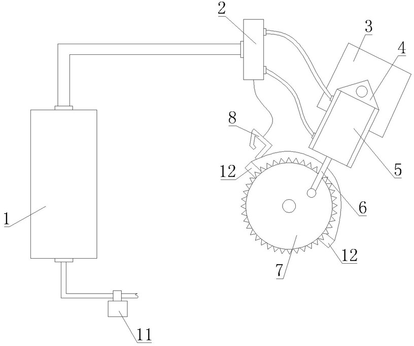
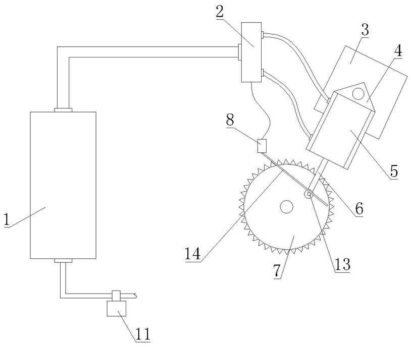
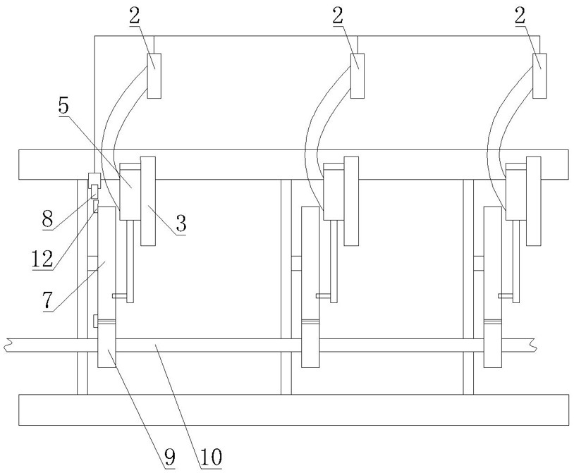
[0016] As shown in the figure, the air pressure-driven power mechanism disclosed by the present invention includes an air storage tank 1, which is connected to an air supply assembly, the air supply assembly includes an air supply pipe connected to the air storage tank 1, and the air supply pipe is connected to an air pump , the air supply pipe is provided with an air supply control valve 11, and the air supply operation of the air storage tank 1 is realized by controlling the opening and closing of the air supply control valve 11. The outlet nozzle of the gas storage tank 1 communicates with the inlet nozzle of the electromagnetic valve 2, and the two first air ports on the electromagnetic ventilation valve 8 communicate with the two second air ports on the driving cylinder correspondingly, and the cylinder body 5 of the driving cylinder is hinged On the frame plate 3 , specifically, the cylinder body 5 of the driving cylinder is connected to the mounting seat 4 , and one end ...


PUM


Abstract

The invention discloses a pneumatic driving type power mechanism. The pneumatic driving type power mechanism is characterized in that the pneumatic driving type power mechanism comprises an air storage tank (1), the air storage tank (1) is connected with an air supply assembly, an air outlet nozzle of the air storage tank (1) communicates with an air inlet nozzle of an electromagnetic valve (2), two first air ports in an electromagnetic air switching valve (8) correspondingly communicate with two second air ports in a drive air cylinder, a cylinder body (5) of the driving air cylinder is hinged to a frame plate (3), a piston rod (6) of the driving air cylinder is eccentrically hinged to a power wheel (7), a rotation detection assembly is arranged on a position close to the power wheel (7), and the rotation detection assembly is electrically connected with the electromagnetic valve (2). The pneumatic driving type power mechanism is simple in structure, reasonable in design and capable of achieving rotation power output driven by the air cylinder.

Description

technical field [0001] The invention relates to power equipment, in particular to a pneumatically driven power mechanism. Background technique [0002] At present, the common power equipment on the market is mainly divided into different types such as pneumatic and electric. One of the pneumatic power mechanisms is driven by a cylinder, but the traditional cylinder-driven mechanism can only provide linear reciprocating power output, and cannot realize the rotational output of power, and the power is relatively small and has relatively large limitations. Contents of the invention [0003] In view of the deficiency of the background technology, the technical problem to be solved by the present invention is to provide a pneumatically driven power mechanism with simple structure, reasonable design, and the ability to realize the output of rotational power driven by the cylinder. [0004] For this reason, the present invention adopts following scheme to realize: [0005] The ...

Claims


Application Information

Patent Timeline
IPC IPC(8): F15B11/06F15B11/08F15B15/04F15B15/06F15B13/04F15B13/044F16H21/18
CPCF15B11/06F15B11/08F15B13/04F15B15/04F15B15/06F15B2013/0448F15B2211/6336F16H21/18
Inventor 林克祥
Owner 林克祥
Learn More