

Array type displacement monitoring system
A displacement monitoring, array-type technology, applied in the direction of measuring devices, measuring acceleration, electromagnetic measuring devices, etc., can solve the problem of high cost
- Summary
- Abstract
- Description
- Claims
- Application Information
AI Technical Summary
Problems solved by technology
Method used
Image

Examples
Embodiment 1
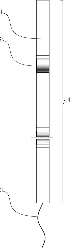
[0042] like figure 1 , 4 In ~6 and 10, an array type displacement monitoring system includes a plurality of monitoring nodes 1, and the monitoring nodes 1 are connected by flexible connecting pipes 2, and an acceleration sensor 100 is arranged in the monitoring nodes 1, such as Figure 4 Among them, the acceleration sensor 100 is electrically connected to the acquisition device 105, and the acquisition device 105 is used to collect signals, and performs filtering and noise reduction processing on the collected electrical signals, and the acquisition device 105 is electrically connected to the computing device 106, and the computing device 106 is used to convert the electrical signals Converted into digital signals, the computing device 106 is electrically connected to the data sending device, and the data sending device uses 485 or CAN bus to send data. With this structure, the present invention is as Figure 14 The arrangement shown in the water conservancy project 9 includ...
Embodiment 2
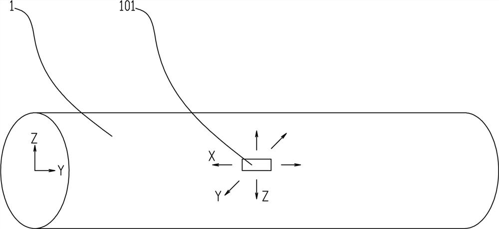
[0044] On the basis of Example 1, the preferred scheme is as figure 2 Among them, a three-axis acceleration sensor 101 is provided in the monitoring section 1 for monitoring the displacement data of the x, y, and z axes. The three-axis acceleration sensor 101 adopts, for example, the ADXL3 series three-axis acceleration sensor, in which a mass block is provided, and the mass block is elastically supported in the orthogonal directions of the x, y, and z axes, and is equipped with a differential capacitance detection The circuit detects the displacement of the mass block, thereby calculating and obtaining the displacement data of the x, y, and z axes.
Embodiment 3
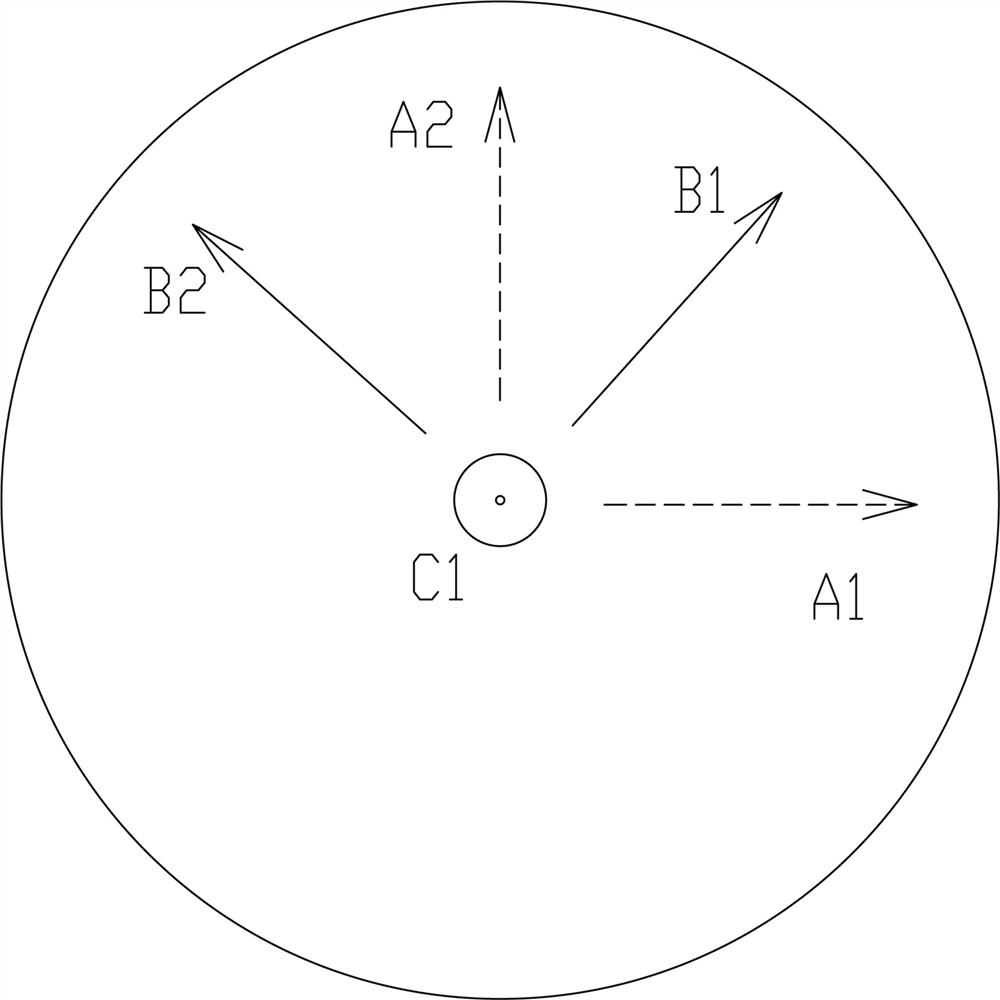
[0046]On the basis of Embodiment 1, in order to avoid the mutual influence among the x, y, and z axes in Embodiment 2, especially the influence of the z axis on the monitoring accuracy of the x, y axes. For example, there is orthogonal interference in the integration of 3 axes, that is, when one of the axes has a large output, even if the other two axes do not actually change, due to the shared demodulation circuit and other issues, the two axes whose actual acceleration does not change will also produce interfere with the output, thereby affecting measurement accuracy. Furthermore, when the acceleration is close to 1g, or when the tilt measurement is in the range of 60-90°, due to the characteristic of the sinusoidal function: the closer the slope is to 90°, the smaller the slope of the curve, and the measurement accuracy will degrade rapidly, greatly affecting the measurement results.
[0047] A further preferred solution is as image 3 Among them, a one-axis acceleration s...
PUM
| Property | Measurement | Unit |
|---|---|---|
| Diameter | aaaaa | aaaaa |
| Outer diameter | aaaaa | aaaaa |
| Wall thickness | aaaaa | aaaaa |
Abstract
Description
Claims
Application Information