Operation positioning device with high precision and positioning method thereof

A positioning device and surgical technology, which is applied in the direction of surgical instrument support, can solve problems such as difficult placement and winding, and achieve the effects of reducing pressure, reducing wear, and ensuring stability and accuracy

Inactive Publication Date: 2021-07-09
潘叨
View PDF1 Cites 0 Cited by
  • Summary
  • Abstract
  • Description
  • Claims
  • Application Information

AI Technical Summary

Problems solved by technology

[0004] The above-mentioned patent has the following disadvantages: it actually utilizes three sets of linear movement components and two sets of rotary drive components to realize the multi-directional movement of the surgical tool end, but its linear drive components and rotary drive components are relatively independent drive units, and The driving force, whether it is a motor, motor, hydraulic rod, etc., requires the arrangement of wiring harness or oil pipe, and when the rotating component rotates, the driving source of the linear moving component will rotate accordingly, and vice versa, which will cause each drive The wiring harness / oil pipe of the source will be entangled with the components, which is difficult to arrange. Therefore, based on this defect, the present invention only solves how to realize the integrated drive of the linear and rotary drives under the condition that the driving source is relatively fixed, so as to ensure that the connecting parts such as the wire harness / oil pipe are not connected. Wrap breakage occurs for easy layout

Method used


Image

  • Operation positioning device with high precision and positioning method thereof
  • Operation positioning device with high precision and positioning method thereof
  • Operation positioning device with high precision and positioning method thereof

Examples


Embodiment 1

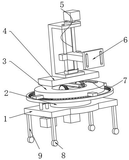
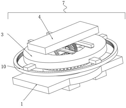
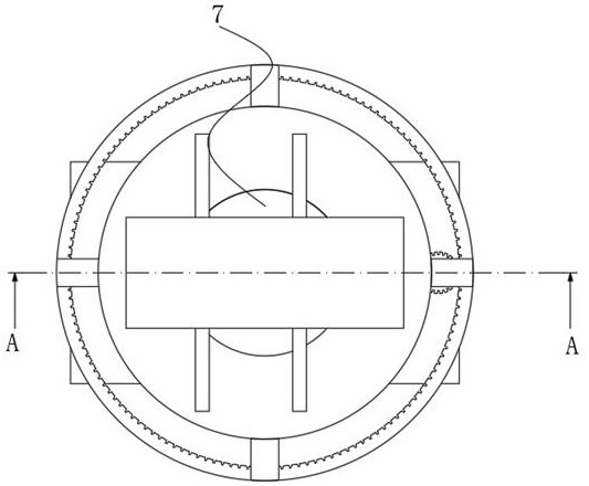
[0040] A surgical positioning device with high precision, such as Figure 1-5As shown, it includes a fixed base 1, the top outer wall of the fixed base 1 is connected with a rotating platform 3 through a rotating drum 2, and the top of the rotating platform 3 is slidably connected with a linear moving platform 4 through a linear slide rail, and the linear moving platform 4 The top of the platform 4 is connected with a surgical instrument mounting seat 6 through a lifting mechanism 5, and the fixed base 1, the rotating platform 3 and the linear moving platform 4 are cooperated through a rotation-translation integrated mechanism 7, and the rotation-translation integrated mechanism 7 includes The intermeshed straight bevel integrated gear 14 and rack two 15, the intermeshed external ring gear 16 and the rotating drive gear 20, the said straight bevel integrated gear 14 is connected to the inner side of the rotary platform 3 through the rotation of the shaft one 13, The second rac...

Embodiment 2

[0047] A surgical positioning device with high precision, such as figure 1 , 6 As shown, in order to solve the lifting problem; this embodiment makes the following improvements on the basis of Embodiment 1: the lifting mechanism 5 includes a lifting frame 26 and a lifting platform 29, and the inner wall of the lifting frame 26 is rotatably connected with two lead screws 28, two lead screws 28 are connected to the inner wall of the lifting platform 29 by threads, and the surgical instrument mounting base 6 is fixed on the outer wall of the lifting platform 29 by bolts, and the top outer wall of one of the leading screws 28 is connected by a coupling The device is connected with a lifting motor 27, and the lifting motor 27 is fixed on the top outer wall of the lifting frame 26 by bolts, and the two leading screws 28 establish transmission cooperation through a synchronous belt 30.

[0048] When this embodiment is in use, when the lifting motor 27 starts, it can drive the screw ...

Embodiment 3

[0050] A method for positioning a surgical positioning device with high precision, the specific steps are as follows:

[0051] S1: fix the surgical instrument on the surgical instrument mount 6;

[0052] S2: After moving the device to the operating room, first start the lifting motor 27 to adjust the approximate height of the surgical instrument mounting seat 6;

[0053] S3: After the height is determined, start the rotating drive motor 22 to adjust the approximate angle of the surgical instrument mounting seat 6;

[0054] S4: Then start the translation drive motor 24 to extend the surgical instrument to the lesion of the patient to be operated on;

[0055] S5: Repeat S2-S4 to complete the final height, angle and distance adjustment to complete the positioning.

[0056] Working principle: when the translation drive motor 24 starts, it drives the bevel gear 25 to rotate through the translation drive shaft 23, thereby driving the straight-cone integrated gear 14 to rotate thro...


PUM


Abstract

The invention discloses a high-precision operation positioning device and a positioning method thereof, and relates to the technical field of operation positioning devices. The problem that a wire harness is wound and damaged due to follow-up of a driving source is solved. The device comprises a fixed base, the outer wall of the top of the fixed base is rotationally connected with a rotating platform through a rotating drum. The method comprises the steps of starting a lifting motor, adjusting the approximate height of a surgical instrument mounting seat, starting a rotating driving motor, adjusting the approximate angle of the surgical instrument mounting seat and then starting a translation driving motor. Due to the fact that the rotation center of the rotating platform coincides with the axis of the translation driving shaft, translation of the linear moving platform depends on the meshing mode of the straight-cone integrated gear and the bevel gear, the linear moving platform does not interfere with each other when rotating and translating, and the two power sources of the linear moving platform can drive the linear moving platform to rotate and translate. Namely, the rotation driving motor and the translation driving motor are in a static state in the rotation and translation processes, so that the wire harness can be effectively prevented from being wound and damaged.

Description

technical field [0001] The invention relates to the technical field of surgical positioning devices, in particular to a high-precision surgical positioning device and a positioning method thereof. Background technique [0002] In today's medical field, there are many operations that require a considerable degree of accuracy, such as the width, depth, length, angle, etc. of the opening of the surgical site in the affected area. It is very likely that very small errors will affect the success of the operation. , and it is not easy to achieve high-precision and error-free operations only through human feeling and judgment during surgery. This requires surgical positioning devices to fix surgical instruments or instruments and assist positioning. [0003] After retrieval, the Chinese Patent Publication No. CN102342857B discloses a surgical positioning device, including a support frame, a vertical linear drive assembly, a horizontal rotary drive assembly, a vertical rotary drive ...

Claims


Application Information

Patent Timeline
IPC IPC(8): A61B90/50
CPCA61B90/50
Inventor 潘叨刘伟
Owner 潘叨
Why Eureka
Try Eureka