
Waste water removal device for machining and using method

A mechanical processing and waste technology, applied in the field of mechanical processing, can solve the problems of incapable of sorting and recycling waste liquid and waste, reducing processing efficiency, unable to realize the synchronization of feeding and discharging processes, etc., to save processing time and improve processing efficiency. Effect

Inactive Publication Date: 2021-07-09
江苏枂硕电子科技有限公司
View PDF0 Cites 0 Cited by
  • Summary
  • Abstract
  • Description
  • Claims
  • Application Information

AI Technical Summary

Problems solved by technology

In mechanical processing, coolant is required, and there will be a certain amount of coolant in the waste generated during cutting. If it is not recycled, it will cause waste and have a certain impact on the sale of waste.
[0003] When removing water from waste, it is necessary to discharge all the waste in the treatment equipment before adding new untreated waste. If the amount of waste to be processed at a time is large, it will consume a lot of work on feeding and discharging. time, the simultaneous feeding and discharging process cannot be realized, and the waste after treatment cannot be sorted and recycled in an orderly manner, which reduces the processing efficiency. For this reason, we propose a waste water removal device for mechanical processing and Instructions

Method used


Image

  • Waste water removal device for machining and using method
  • Waste water removal device for machining and using method
  • Waste water removal device for machining and using method

Examples


Embodiment 1

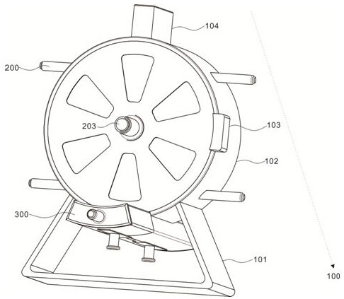
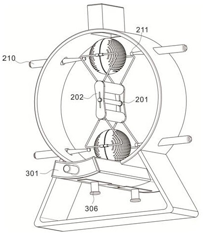
[0028] Example 1: Please refer to figure 1 and figure 2 , the present invention provides a waste water removal device for mechanical processing, including a housing assembly 100, including a support frame 101, the top of the support frame 101 is fixedly connected to the shell 102, the top of the shell 102 is provided with a feed channel 104, and the surface of the shell 102 is respectively A feed port and a discharge port are provided, and a control box 103 is provided on the side wall of the casing 102; the water removal assembly 200 includes a rotating shaft 201 that is movably inserted into the inner cavity of the casing 102, and the end of the rotating shaft 201 runs through the casing 102 and is connected to the drive The output end of the motor 203 is connected to the collection assembly 300 , and the collection assembly 300 is arranged at the bottom of the housing 102 .

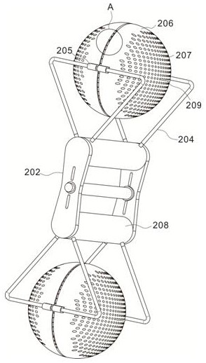
[0029] The two ends of the rotating shaft 201 are fixedly connected with the movable plate 202, a...

Embodiment 2

[0034] Example 2: Please refer to figure 2 and Figure 5 The collection assembly 300 includes a guide frame 301 fixed on the bottom of the casing 102 close to the discharge port. The inner cavity of the guide frame 301 is symmetrically provided with a slidable collection box 302 and a water collection box 303. Between the collection box 302 and the water collection box 303 They are linked by connecting rod 304, and the collection box 302 is controlled to move in the guide frame 301 by the push cylinder 305. When the dome cover 206 is running at high speed, the push cylinder 305 drives the water collection box 303 to move to the discharge of the shell 102. Below the outlet, the filtered liquid is collected, and when the waste is discharged, the collection box 302 is driven to move to the bottom of the outlet, so that the water removal operation is carried out in an orderly manner. The bottom of the collection box 302 and the water collection box 303 are equipped with outlet pi...


PUM


Abstract

The invention discloses a waste water removal device for machining and a using method, and belongs to the technical field of machining. The waste water removal device comprises a shell assembly, a water removal assembly and a collecting assembly. The top end of a supporting frame is fixedly connected with a shell, a feeding channel is formed in the top of the shell, and a control box is arranged on the side wall of the shell. The water removal assembly comprises a rotating shaft which is movably inserted into the inner cavity of the shell, and the end part of the rotating shaft penetrates through the shell and is connected with the output end of a driving motor. The collecting assembly is arranged at the bottom of the shell. A cylinder rod drives a cylinder clamping jaw to move towards a concave pull rod and clamp the concave pull rod, then hemispherical covers are reset and in butt joint under the action of an elastic cloth layer and a spring, the rotating shaft is driven to drive a movable plate to rapidly rotate in the inner cavity of the shell, water contained in waste flows out through water filtering holes in one hemispherical cover under the centrifugal action, waste in the other hemispherical cover is synchronously dewatered, the discharging operation is completed while feeding is conducted, the feeding process and the discharging process are conducted synchronously and alternately, the treatment time is saved, and the treatment efficiency is improved.

Description

technical field [0001] The invention relates to the technical field of mechanical processing, in particular to a waste material dewatering device for mechanical processing and a use method. Background technique [0002] The production process of a machine refers to the entire process of making a product from raw materials. For machine production, it includes transportation and storage of raw materials, production preparation, blank manufacturing, processing and heat treatment of parts, product assembly, debugging, painting and packaging, etc. The content of the production process is very extensive. Modern enterprises use the principles and methods of systems engineering to organize and guide production, and regard the production process as a production system with input and output. In mechanical processing, coolant is required, and there will be a certain amount of coolant in the waste generated during cutting. If it is not recycled, it will cause waste and have a certain i...

Claims


Application Information

Patent Timeline
Patent Type & Authority Applications(China)
IPC IPC(8): B01D33/27B01D33/37
CPCB01D33/27B01D33/37
Inventor 程小龙常耀方
Owner 江苏枂硕电子科技有限公司
Learn More