
Water circulation equipment for raising dust control and working method thereof

A technology of water circulation and equipment, which is applied in the field of water circulation equipment for dust control, can solve the problems of inconvenient adjustment of water spray angle range, inconvenient dust collection and treatment, and influence on the smooth progress of dust reduction, so as to facilitate sufficient dust reduction, facilitate unified cleaning, reduce The effect of repeated dust

Pending Publication Date: 2021-07-09
BOZHOU UNIV
View PDF0 Cites 0 Cited by
  • Summary
  • Abstract
  • Description
  • Claims
  • Application Information

AI Technical Summary

Problems solved by technology

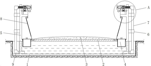
[0007] The purpose of the present invention is to provide a water circulation equipment for dust control and its working method to solve the problem that the existing dust control device proposed in the above background technology cannot effectively and quickly carry out dust reduction treatment for the dust on the dusty construction site in a timely manner. At the same time, it is not convenient to collect and process the dust, and it is easy to repeatedly raise dust, which affects work efficiency. Generally, the water spray is used to reduce dust, and the water spray head is prone to clogging, which affects the smooth progress of the dust reduction work, affects the use, and is not convenient for the water spray. Adjusting the angle range makes it inconvenient to fully reduce dust and affect the use. At the same time, it is inconvenient to fully filter the mixture of water and dust, and it is impossible to recycle the sewage, which is easy to cause waste of water and affect the use of the problem.

Method used


Image

  • Water circulation equipment for raising dust control and working method thereof
  • Water circulation equipment for raising dust control and working method thereof
  • Water circulation equipment for raising dust control and working method thereof

Examples


Embodiment Construction

[0048] The following will clearly and completely describe the technical solutions in the embodiments of the present invention with reference to the accompanying drawings in the embodiments of the present invention. Obviously, the described embodiments are only some, not all, embodiments of the present invention. Based on the embodiments of the present invention, all other embodiments obtained by persons of ordinary skill in the art without making creative efforts belong to the protection scope of the present invention.

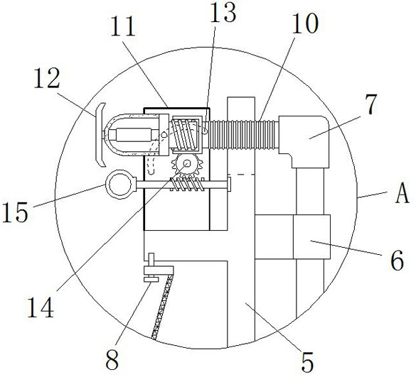
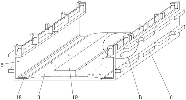
[0049] see Figure 1-8 , the present invention provides a technical solution: a water circulation equipment for dust control and its working method, including a water tank pit 1, a reinforced base layer 2, a drainage layer 3, a drainage board 4, a supporting wall board 5, a fixing board 6, and connecting water pipes 7. Filter plate 8, water pump 9, connecting hose 10, limit plate 11, high-pressure atomizing nozzle 12, limit chute 13, worm wheel 14, worm 15, fl...


PUM


Abstract

The invention discloses water circulation equipment for raising dust control and a working method thereof. The water circulation equipment comprises a water accumulation groove pit, a drainage plate, a connecting water pipe and a fixed cover plate. A reinforcing base layer is poured on the upper end face of the water accumulation groove pit, and meanwhile, limiting clamping grooves are formed in the left side and the right side of the reinforcing base layer. The lower end of the drainage plate is fixedly connected with a filter screen. The lower end of the connecting water pipe is connected with a water pump, and the upper end of the connecting water pipe is connected with a high-pressure atomizing nozzle through a connecting hose. The fixed cover plate is fixedly mounted on the upper surface of the drainage layer. According to the water circulation equipment for raising dust control and the working method thereof, dust falling treatment can be effectively and quickly carried out in time, meanwhile, dust can be conveniently collected and treated, repeated raising dust is reduced, the working efficiency is improved, the blocking phenomenon is generally avoided by water spraying dust falling and water spraying head protection, the mixture of water and dust can be fully and conveniently filtered, and sewage can be conveniently recycled.

Description

technical field [0001] The invention relates to the technical field related to dust control, in particular to a water circulation device for dust control and a working method thereof. Background technique [0002] Dust control is very important on the construction site. The main means of transportation that cause dust is the muck truck. It is a truck that transports construction materials such as sand and gravel. When the muck truck is moving forward on the construction site, it will generate a large amount of dust, which will cause the dust to fly on the construction site and affect the breathing health of the workers. Therefore, many construction sites will introduce muck trucks to control dust. The device can effectively control the dust, avoid dust, and facilitate the safe driving of vehicles to ensure the safe use of the construction site. [0003] However, the existing dust control devices are prone to large and small problems in the actual use process, which affect t...

Claims


Application Information

Patent Timeline
Patent Type & Authority Applications(China)
IPC IPC(8): B01D47/06B01D29/03
CPCB01D29/03B01D47/06B01D2247/04
Inventor 江浩王玉民刘虎宋洪福
Owner BOZHOU UNIV
Learn More