Unlock instant, AI-driven research and patent intelligence for your innovation.

Data encoding method and apparatus, data decoding method and apparatus, data recording medium, and data transmission method

An information encoding and information decoding technology, applied in transmission systems, information storage, recorded information storage, etc., can solve the problems of increased sound quality deterioration, high compression rate, difficult sound quality deterioration, etc., to achieve high efficiency and prevent pre-echoes. Effect

Inactive Publication Date: 2003-12-10
SONY CORP
View PDF1 Cites 0 Cited by
  • Summary
  • Abstract
  • Description
  • Claims
  • Application Information

AI Technical Summary

Problems solved by technology

The pre-echo is caused by the quantization noise that occurs in the frequency domain and is transformed into the time domain. Therefore, if the compression rate of the encoding increases, the quantization noise in the frequency domain increases, and the sound quality deterioration caused by the pre-echo will also increase. On the one hand, if the gain control is not necessary, the energy distribution in the frequency region will be diffused, so it is not desirable for effective compression
Therefore, it is difficult to prevent the sound quality from deteriorating especially when the compression ratio is high, using the conventional method of selecting whether to perform gain control of a specified value according to whether or not a high-pitched part is detected.

Method used


Image

  • Data encoding method and apparatus, data decoding method and apparatus, data recording medium, and data transmission method
  • Data encoding method and apparatus, data decoding method and apparatus, data recording medium, and data transmission method
  • Data encoding method and apparatus, data decoding method and apparatus, data recording medium, and data transmission method

Examples


Embodiment Construction

[0098] Hereinafter, an excellent embodiment of the present invention will be described with reference to the accompanying drawings.

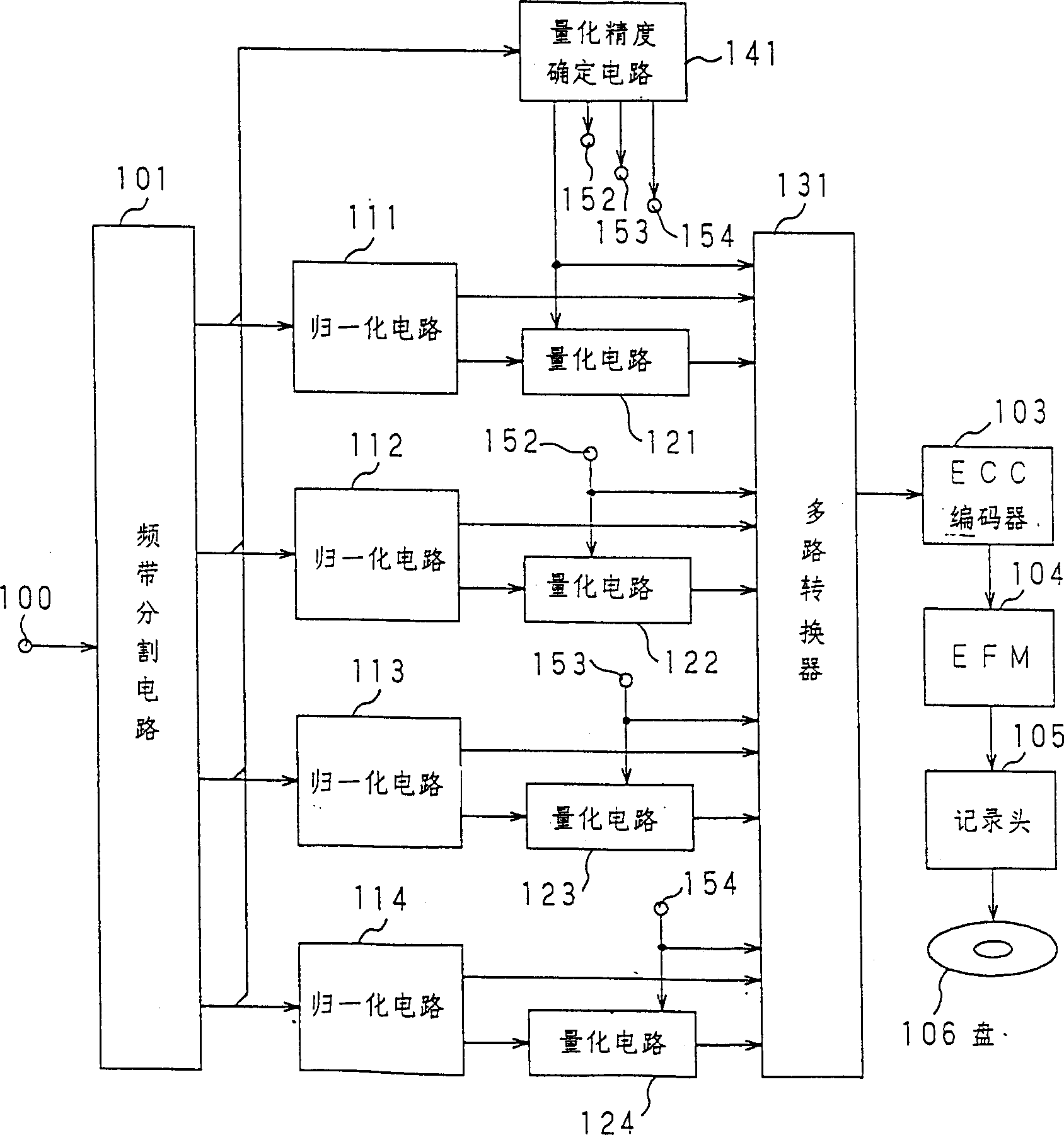
[0099] figure 1 is a circuit block diagram of an embodiment of an encoding device to which the information encoding method of the present invention is applied.

[0100] exist figure 1 Among them, the audio signal input to the encoding device through the input terminal 100 is subjected to band division by the band division circuit 101 . As the band dividing method of the band dividing circuit 101, the above-mentioned filter dividing method such as QMF may be used, or a method of grouping spectral components obtained by spectral transformation such as MDCT into frequency bands may be used. In addition, a method of temporarily performing spectral conversion on an audio signal divided into several frequency bands by a filter, and then grouping the obtained spectral components into each frequency band may also be used. In addition, the width of ...


PUM


Abstract

A signal encoding process comprises the steps of determining a gain control function of an overlapping portion of the present block on the basis of a gain control function of the previous block at the overlapping portion of the present block and the previous block of an input waveform signal; controlling the gain of the input waveform signal corresponding to the present block by using the gain control function of the overlapping portion; extracting a sample overlapping between adjacent blocks on the time axis to convert the sample to a signal on the frequency axis; encoding the converted signal and the control data for gain control; and outputting the encoded signal. A signal decoding process comprises the steps of decoding the encoded signal to take out the conversion signal and the control data; effecting inverse conversion for the converted signal by the interference of the waveform elements between the adjacent blocks; determining the gain control function of the overlapping portion of the present block on the basis of the control data and the gain control function of the previous block at the overlapping portion between the present block and the previous block; controlling the gain of the inversely converted signal corresponding to the present block by using the gain control function of the overlapping portion; and restoring the original waveform signal. According to this method, the amplification in the encoding and the corresponding correction in the decoding can be performed without any contradiction between the blocks in the case or the interference of the waveform elements of both adjacent blocks at the time of inverse conversion such as MDCT, so that the occurence of the pre-echo can be prevented by a simple construction using spectrum conversion having high encoding efficiency.

Description

technical field [0001] The present invention relates to an information encoding method and device, an information decoding method and device, an information recording medium and Information transfer method. Background technique [0002] Hitherto, various methods for high-efficiency coding of audio or sound signals have been known, for example, non-blocking frequency bands that do not block audio signals on the time axis but divide them into multiple frequency bands and encode them Band split coding (segmented band coding: SBC) by split method, and block band split method that converts a signal on the time axis into a signal on the frequency axis (spectrum conversion) and then divides it into multiple frequency bands and encodes each band are so-called transformation coding, etc. In addition, a high-efficiency coding method that combines the above-mentioned frequency band division coding and transform coding can also be considered. The signal on the spectrum transform is c...

Claims


Application Information

Patent Timeline
Patent Type & Authority Patents(China)
IPC IPC(8): G10L19/02G11B20/10H04B1/66
CPCG10L19/0212H04B1/665G11B20/10527
Inventor 筒井京弥R·赫德尔
Owner SONY CORP