Supercharge Your Innovation With Domain-Expert AI Agents!

Hybrid module of vehicle

A hybrid power module and vehicle technology, applied in the field of vehicles, can solve the problems of easily fouling other parts, increase the complexity of the installation process, etc., and achieve the effect of simple structure

Pending Publication Date: 2021-07-09
SCHAEFFLER TECH AG & CO KG
View PDF0 Cites 0 Cited by
  • Summary
  • Abstract
  • Description
  • Claims
  • Application Information

AI Technical Summary

Problems solved by technology

[0005] However, the application of anti-loose glue increases the complexity of the installation process on the one hand, and on the other hand, it is easy to contaminate other parts

Method used


Image

  • Hybrid module of vehicle
  • Hybrid module of vehicle
  • Hybrid module of vehicle

Examples


Embodiment Construction

[0026] Exemplary embodiments of the present invention are described below with reference to the accompanying drawings. It should be understood that these specific descriptions are only used to teach those skilled in the art how to implement the present invention, but are not intended to exhaust all possible ways of the present invention, nor are they intended to limit the scope of the present invention.

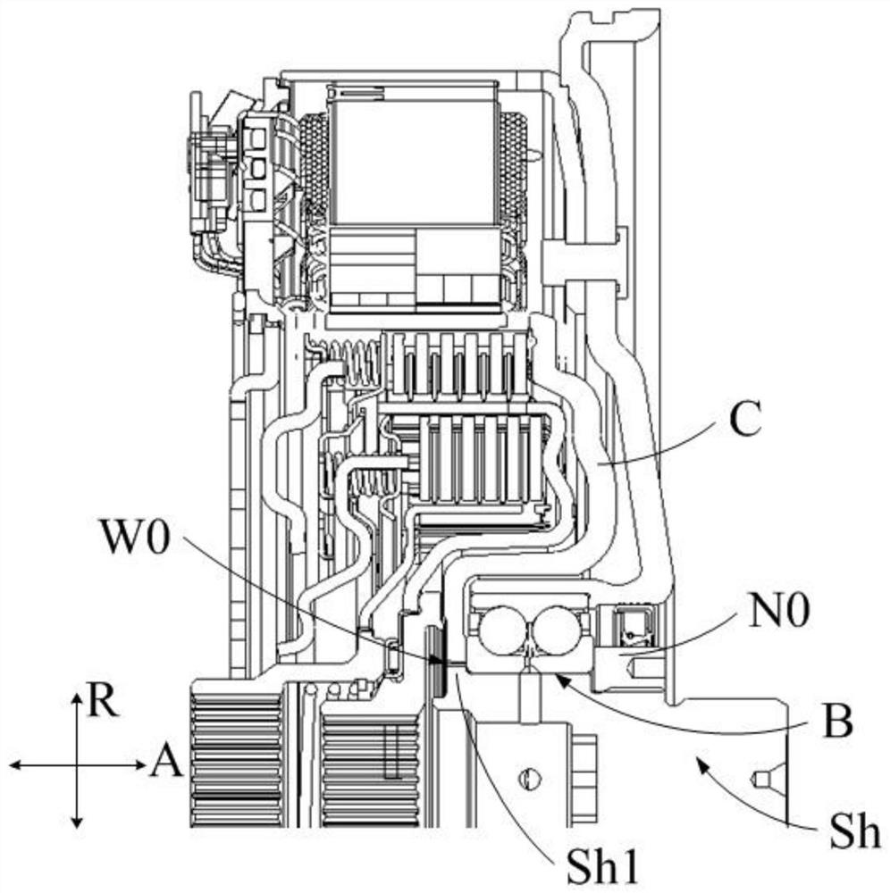
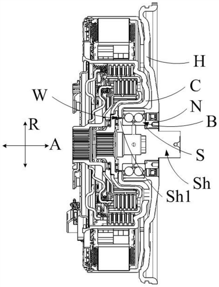
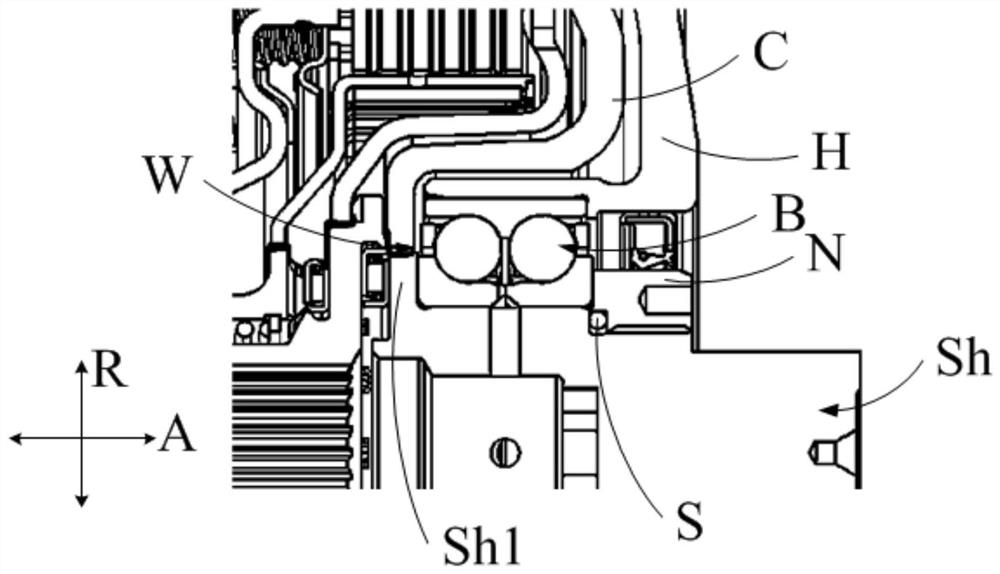
[0027] refer to figure 2 and image 3 A hybrid module for a vehicle according to the invention is presented. Unless otherwise specified, A in the figure represents the axial direction of the hybrid power module of the vehicle, and the axial direction A is consistent with the axial direction of the transmission shaft Sh; R represents the radial direction of the hybrid power module of the vehicle, and the radial direction R is consistent with the axial direction of the transmission shaft Sh radially consistent.

[0028] In this embodiment, the hybrid module is, for example,...


PUM


Abstract

The invention provides a hybrid module of a vehicle. The hybrid module comprises a transmission shaft (Sh), a bearing (B), a nut (N), and a rotor holder (C); the rotor holder (C) is in non-rotatable connection with a rotor of a motor;a flange portion (Sh1) is formed in the transmission shaft (Sh);the transmission shaft (Sh) is in non-rotatable connection with the rotor holder (C) at the flange portion (Sh1); the bearing (B) is attached to the transmission shaft (Sh); in an axial direction (A) of the flange portion (Sh1), one end of the bearing (B) abuts against the flange portion (Sh1), the other end of the bearing (B) abuts against the nut (N), the nut (N) is installed on the transmission shaft (Sh) and applies axial force to the bearing (B), and the end of the bearing (B) does not make contact with the area where the flange portion (Sh1) and the rotor holder (C) are connected. According to the hybrid power module of the vehicle, the structure is simple, the installation process is simple, and positioning of parts is reliable.

Description

technical field [0001] The invention relates to the field of vehicles, in particular to a hybrid power module of a vehicle. Background technique [0002] figure 1 A P1 hybrid module is shown, the electric motor of which is located before the gearbox, mounted on the crankshaft of the engine, and the whole of the module is located before the K0 clutch. The module consists of the transmission shaft Sh, the rotor support C of the motor, the bearing B and the nut N0. [0003] One end of the drive shaft Sh is welded to the rotor support C, and the welded area forms an annular weld W0. The bearing B is sleeved on the transmission shaft Sh, and one end of the bearing B abuts against the rotor support C, and the other end abuts against the nut N0 so as to be positioned in the axial direction A. In other words, the locking force of the nut N0 presses the bearing B against the rotor bracket C. [0004] However, since the bearing B presses against the weld seam W0, and the pressure ...

Claims


Application Information

Patent Timeline
IPC IPC(8): B60K6/36B60K6/26B60K6/24
CPCB60K6/24B60K6/26B60K6/36Y02T10/62
Inventor 李欣刘兴芬邓承毅
Owner SCHAEFFLER TECH AG & CO KG
Features
  • R&D
  • Intellectual Property
  • Life Sciences
  • Materials
  • Tech Scout
  • Unparalleled Data Quality
  • Higher Quality Content
  • 60% Fewer Hallucinations
Learn More