
High-airtightness, high-protection-grade and high-compactness lighting device

A compact lighting and high-protection technology, applied in the field of lighting, can solve the problems of insufficient process execution, substandard waterproof effect, and substandard assembly products, etc., to simplify installation and production processes, avoid human factors and raw material factors, The effect of prolonging the service life

Inactive Publication Date: 2021-07-09
SHANGHAI BINY ELECTRIC
View PDF11 Cites 0 Cited by
  • Summary
  • Abstract
  • Description
  • Claims
  • Application Information

AI Technical Summary

Problems solved by technology

However, the existing spotlight lamps have the following defects, but for LED lamps, waterproof and heat dissipation have always been problems that every manufacturer must seriously solve. If these two problems are not solved well, they will directly affect the life of the lamps.
[0003] At present, most of the floodlights on the market adopt the waterproof method of structural sealing, glue sealing or a combination of the two. , or the quality of the material itself, resulting in the assembly of the product is not in place, causing the waterproof effect to fail to meet the standard. At the same time, the original spray waterproof test method takes up to 30 minutes, which is only suitable for random inspection, not for full inspection.
[0004] The heat dissipation structures of existing lamps are basically aluminum radiators, which can dissipate heat through natural conduction and natural convection. This kind of heat dissipation is satisfactory for most lamps, but it should also be a simple structure, which also limits the shape and structure of lamps. space for play; for example: most lamps and lanterns on the market are installed separately for power supply and light source, so that the heat of the light source and the power supply do not affect each other; this kind of structural lamp not only needs many auxiliary parts besides the necessary accessories, but also has a complex structure , the assembly process is cumbersome; and the power cavity is separated from the light source cavity, and an external connection cable is required between the two, and the waterproof structure of the cable needs to be considered. At the same time, the exposed cable is easy to age, which affects the service life

Method used


Image

  • High-airtightness, high-protection-grade and high-compactness lighting device
  • High-airtightness, high-protection-grade and high-compactness lighting device
  • High-airtightness, high-protection-grade and high-compactness lighting device

Examples


Embodiment 1

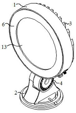
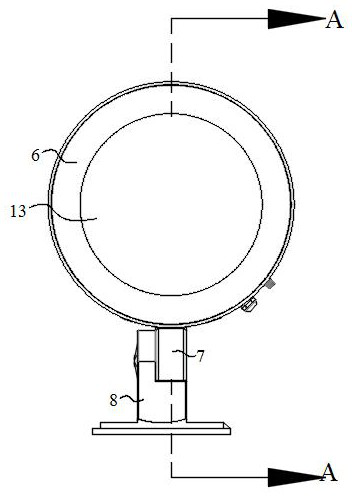
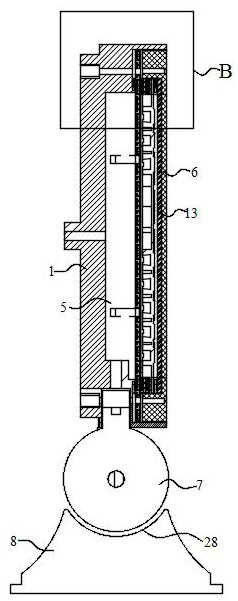
[0036] refer to Figure 1-8 , high airtightness, high protection level, and high compact lighting device, including a housing 1, a connecting plate 10, a cover plate 6, a light source assembly, and a power supply assembly 5; The side plate 14 on the side is composed of a cavity structure, and the surface of the bottom plate 15 facing the inside of the cavity structure is the front; the connecting plate 10 is arranged in the cavity structure of the housing 1 and divides the cavity structure into a power supply cavity. and the light source cavity, the connecting plate 10 includes a first side and a second side, and the face opposite to the front of the bottom plate 15 is the first side; between the first side of the connecting plate 10 and the front of the bottom plate 15 The power supply chamber is formed, and the power supply chamber is used to accommodate the power supply assembly 5; a heat conduction pipe 25 is arranged in the power supply chamber, and the heat conduction pi...

Embodiment 2

[0051] refer to Figure 9 with Figure 10 , the first lateral surface of the supporting base 2 of the lighting device in this embodiment is fixedly connected to the bottom plate 15 of the casing 1, and the rest are the same as in the first embodiment.

Embodiment 3

[0053] The vacuum pumping principle of the lighting device of the present invention:

[0054] refer to Figure 8 , by pressing the core rod 35 at the air outlet end of the valve core, the spring 34 is compressed, and at the same time, the core seat sealing ring 38 and the first stopper 39 leave the first positioning portion 37, and the intake air of the valve core airflow channel 33 The opening is opened to connect the inside and outside of the lighting device. After the air in the cavity of the lighting device is sucked out by vacuum equipment, the pressure is removed. The first positioning part 37 of the valve core moves until it touches it completely, and the air inlet of the airflow channel 33 of the valve core is sealed again, so that the cavity is in a vacuum state.


PUM


Abstract

A high-airtightness, high-protection-grade and high-compactness lighting device comprises a shell, a connecting plate, a cover plate, a light source assembly and a power source assembly. The shell is composed of a bottom plate and side plates and is of a cavity structure, the connecting plate is arranged in the shell and divides the cavity structure into a power source cavity and a light source cavity, and the connecting plate comprises a first side surface and a second side surface. A heat-conducting pipe is arranged in the power source cavity, a first connecting end of the heat-conducting pipe is contacted with the front surface of the bottom plate, and a second connecting end of the heat-conducting pipe is contacted with a first side surface of the connecting plate; a plurality of convex parts are arranged on the first side surface of the connecting plate, and the power source assembly is fixed on the convex parts, so that the power source assembly is in a suspended state in the power source cavity and is not in contact with the heat-conducting pipe and the connecting plate; radiating fins are arranged on the back surface of the bottom plate; the light source assembly is attached to the second side surface of the connecting plate in the light source cavity, so that heat emitted by the light source assembly is conducted to the radiating fins through the connecting plate and the heat-conducting pipe for heat dissipation; and a valve core is arranged on the shell and used for extracting gas in the lighting device, so that the interior of the lighting device is in a vacuum state.

Description

technical field [0001] The invention relates to the technical field of lighting, in particular to a highly airtight, high-protection level, and compact lighting device. Background technique [0002] Lamps, especially the floodlights among them, are a kind of lamps that converge the light from the light source and project them in a designated direction to achieve regional lighting. It is often used in square lighting, large-area operation lighting, exterior wall lighting of historical buildings, indoor local lighting and other scenes. However, the existing spotlight lamps have the following defects, but for LED lamps, waterproof and heat dissipation have always been problems that every manufacturer must seriously solve. If these two problems are not solved well, they will directly affect the life of the lamps. [0003] At present, most of the floodlights on the market adopt the waterproof method of structural sealing, glue sealing or a combination of the two. , or the quali...

Claims


Application Information

Patent Timeline
Patent Type & Authority Applications(China)
IPC IPC(8): F21S9/00F21V15/01F21V29/10F21V23/00F21V19/00F21V31/00F21V29/76F21V29/71F21V29/503F21V21/30F21V21/104F21V21/00
CPCF21S9/00F21V15/01F21V29/10F21V23/023F21V19/00F21V23/002F21V31/005F21V29/763F21V29/713F21V29/503F21V21/30F21V21/104F21V21/00
Inventor 严少斌严飞飞高向东刘明生侯成新陈乾君刘海涛
Owner SHANGHAI BINY ELECTRIC
Learn More