Precision illumination optical system, device and method
A technology for lighting optical systems and lighting devices, applied in the field of precise lighting optical systems, can solve problems such as glare, light waste, dark areas, etc., and achieve the effects of prolonging service life, avoiding direct sunlight, and improving light-cutting effect.
- Summary
- Abstract
- Description
- Claims
- Application Information
AI Technical Summary
Problems solved by technology
Method used
Image
Examples
Embodiment 1
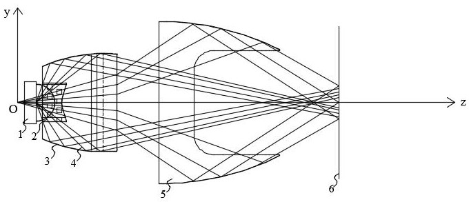
[0051] refer to figure 1 , a precision lighting optical system, the optical system includes an LED light source 1, a total reflection lens 3 and a reflector 5; The short axis is the Y axis; the total reflection lens 3 has a light incident surface 17 and a light exit surface 20, and the light incident surface of the total reflection lens 3 encloses a cavity structure, which constitutes an optical system for accommodating the light emitting surface of the LED light source 1. Cavity 18, the surface of the optical cavity 18 opposite to the LED light source 1 is a convex arc surface, the line connecting the vertices of the arc surface is parallel to the X axis; the light exit surface 20 of the total reflection lens 3 is two A free-form surface with convex sides and concave in the middle, the line connecting the vertices of the convex surface on each side of the free-form surface and the connecting line between the vertices of the concave surface in the middle are all parallel to th...
Embodiment 2
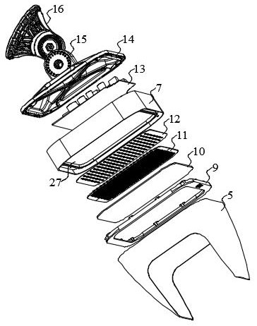
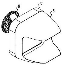
[0056] see figure 2 , a precision lighting device, the precision lighting device includes a light source assembly, a power supply assembly 13, a housing body 7 and a support base 8, the optical system in the first technical solution of the light source assembly is composed of LED light sources 1 arrayed in the optical system The LED luminescent plate 12, the lens module 11 composed of the total reflection lens 3 of the array and the reflector 5 are composed.
[0057] In a preferred but non-limiting embodiment of the present invention, see Figure 2-Figure 5 , the housing main body 7 of the lighting device has a cavity structure, and a partition 27 is arranged inside the cavity structure of the housing main body 7, and the partition 27 divides the cavity structure into a light source cavity and a power supply cavity. The light source chamber is used to accommodate the light-emitting assembly composed of the LED light-emitting board 12 and the lens module 11 in the light sourc...
Embodiment 3
[0066] The precise lighting method includes the optical system in the first technical solution, and the method includes the following steps:
[0067]Step 1, realize the primary light distribution by directly packaging the light-emitting diode and the primary lens together, and obtain the LED light source 1 with a specified beam angle;
[0068] Step 2, by disposing a total reflection lens 3 on the light-emitting surface side of the LED light source 1 obtained in the step 1, using the arc-shaped curved light incident surface 17, the total emission outer peripheral surface 19 and the free-form surface of the total reflection lens 3 The light output surface 20 performs secondary light distribution, which can collect all the light emitted from the LED light source 1, and evenly redistribute most of the light emitted from the LED light source 1 to the target beam angle;
[0069] Step 3, by configuring the reflector 5 on the light-emitting surface 20 side of the total reflection lens...
PUM
| Property | Measurement | Unit |
|---|---|---|
| transmittivity | aaaaa | aaaaa |
Abstract
Description
Claims
Application Information
 - R&D
- Intellectual Property
- Life Sciences
- Materials
- Tech Scout
- Unparalleled Data Quality
- Higher Quality Content
- 60% Fewer Hallucinations
Browse by: Latest US Patents, China's latest patents, Technical Efficacy Thesaurus, Application Domain, Technology Topic, Popular Technical Reports.
© 2025 PatSnap. All rights reserved.Legal|Privacy policy|Modern Slavery Act Transparency Statement|Sitemap|About US| Contact US: help@patsnap.com


