
Precise illumination optical system, device and method

A lighting optical system and lighting device technology, applied in the field of precise lighting optical system, can solve problems such as dark areas, glare, light waste, etc., achieve good light cutting effect, prolong service life, and avoid direct sunlight

Active Publication Date: 2021-01-26
SHANGHAI BINY ELECTRIC
View PDF7 Cites 0 Cited by
  • Summary
  • Abstract
  • Description
  • Claims
  • Application Information

AI Technical Summary

Problems solved by technology

However, since most LEDs are generally considered to be approximate Lambertian light sources, if there is no light distribution, the light pattern shining on the ground will become a large circular spot, not only a lot of light is wasted in the non-illumination range , at the same time, there will be an obvious dark area at the junction of the light spots, and it will cause glare to distant vehicles or pedestrians, so

Method used


Image

  • Precise illumination optical system, device and method
  • Precise illumination optical system, device and method
  • Precise illumination optical system, device and method

Examples


Embodiment 1

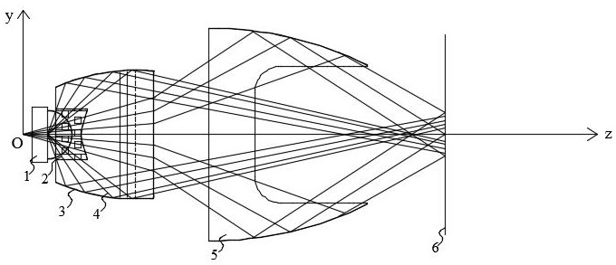
[0051] refer to figure 1 , a precision lighting optical system, the optical system includes an LED light source 1, a total reflection lens 3 and a reflector 5; The short axis is the Y axis; the total reflection lens 3 has a light incident surface 17 and a light exit surface 20, and the light incident surface of the total reflection lens 3 encloses a cavity structure, which constitutes an optical system for accommodating the light emitting surface of the LED light source 1. Cavity 18, the surface of the optical cavity 18 opposite to the LED light source 1 is a convex arc surface, the line connecting the vertices of the arc surface is parallel to the Y axis; the light exit surface 20 of the total reflection lens 3 is two A free-form surface with convex sides and concave in the middle, the line connecting the vertices of the convex surface on each side of the free-form surface and the connecting line between the vertices of the concave surface in the middle are all parallel to th...

Embodiment 2

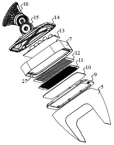
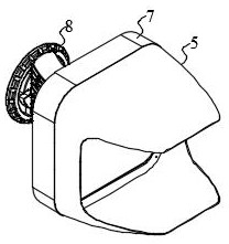
[0056] see figure 2 , a precision lighting device, the precision lighting device includes a light source assembly, a power supply assembly 13, a housing body 7 and a support base 8, the optical system in the first technical solution of the light source assembly is composed of LED light sources 1 arrayed in the optical system The LED luminescent plate 12, the lens module 11 composed of the total reflection lens 3 of the array and the reflector 5 are composed.

[0057] In a preferred but non-limiting embodiment of the present invention, see Figure 2-Figure 5 , the housing main body 7 of the lighting device has a cavity structure, and a partition 27 is arranged inside the cavity structure of the housing main body 7, and the partition 27 divides the cavity structure into a light source cavity and a power supply cavity. The light source chamber is used to accommodate the light-emitting assembly composed of the LED light-emitting board 12 and the lens module 11 in the light sourc...

Embodiment 3

[0066] The precise lighting method includes the optical system in the first technical solution, and the method includes the following steps:

[0067]Step 1, realize the primary light distribution by directly packaging the light-emitting diode and the primary lens together, and obtain the LED light source 1 with a specified beam angle;

[0068] Step 2, by disposing a total reflection lens 3 on the light-emitting surface side of the LED light source 1 obtained in the step 1, using the arc-shaped curved light incident surface 17, the total emission outer peripheral surface 19 and the free-form surface of the total reflection lens 3 The light output surface 20 performs secondary light distribution, which can collect all the light emitted from the LED light source 1, and evenly redistribute most of the light emitted from the LED light source 1 to the target beam angle;

[0069] Step 3, by configuring the reflector 5 on the light-emitting surface 20 side of the total reflection lens...


PUM

PropertyMeasurementUnit
transmittivityaaaaaaaaaa

Abstract

The invention relates to an accurate illumination optical system, device and method. The optical system comprises an LED light source, a total reflection lens and a reflector. The total reflection lens is provided with a light-in surface and a light-out surface, the light-in surface of the total reflection lens defines a cavity structure to form an optical cavity for accommodating the light-emitting surface of the LED light source, the surface, opposite to the LED light source, of the optical cavity is a convex arc-shaped curved surface, and the light-out surface of the optical cavity is a free curved surface with two convex sides and a concave middle part; the outer peripheral surface of the optical cavity is a fully reflecting surface capable of reflecting light; the reflector is arranged on the light emitting surface side of the total reflection lens; the reflector is provided with a light inlet, a light outlet and a reflection inner side wall extending between the light inlet and the light outlet. According to the design of the optical system, rectangular light spots are finally formed on a target surface, the staggered diffusion uniformity of emergent light rays is good, meanwhile, a good light interception effect is achieved, glare is effectively restrained, light pollution is reduced, and accurate illumination is achieved.

Description

technical field [0001] The invention relates to a precision illumination optical system, device and method thereof. Background technique [0002] LED street lamps have become the trend of technological development due to their small size, long life, high electro-optic efficiency, environmental protection and energy saving. There are many places in special spaces such as outdoor stadiums, airports, and port terminals, where lighting needs to be well controlled, especially port terminals. In the entire port terminal area, the ambient lighting needs to be uniform, but in the port loading and unloading equipment area, it is necessary to precisely control the light within the lighting range below the equipment to reduce the interference of light on human vision and reduce light pollution. However, since most LEDs are generally considered to be approximate Lambertian light sources, if there is no light distribution, the light pattern shining on the ground will become a large circ...

Claims


Application Information

Patent Timeline
Patent Type & Authority Applications(China)
IPC IPC(8): F21S8/04F21V13/04F21V5/00F21V5/04F21V7/04F21V7/28F21V15/01F21V19/00F21V21/30F21V29/89F21Y115/10F21W131/10
CPCF21S8/043F21V5/007F21V5/045F21V7/04F21V13/04F21V15/01F21V19/003F21V21/30F21W2131/10F21V29/89F21Y2115/10F21V7/28
Inventor 严少斌严飞飞刘明生高向东侯成新陈乾君刘海涛
Owner SHANGHAI BINY ELECTRIC
Learn More