A kind of visible light cutting film, its preparation method and application
A technology of visible light and absorbing film, which is applied in the field of optical film, can solve the problems of poor cut-off effect of visible light and achieve good visual effect
- Summary
- Abstract
- Description
- Claims
- Application Information
AI Technical Summary
Problems solved by technology
Method used
Image
Examples
preparation example Construction
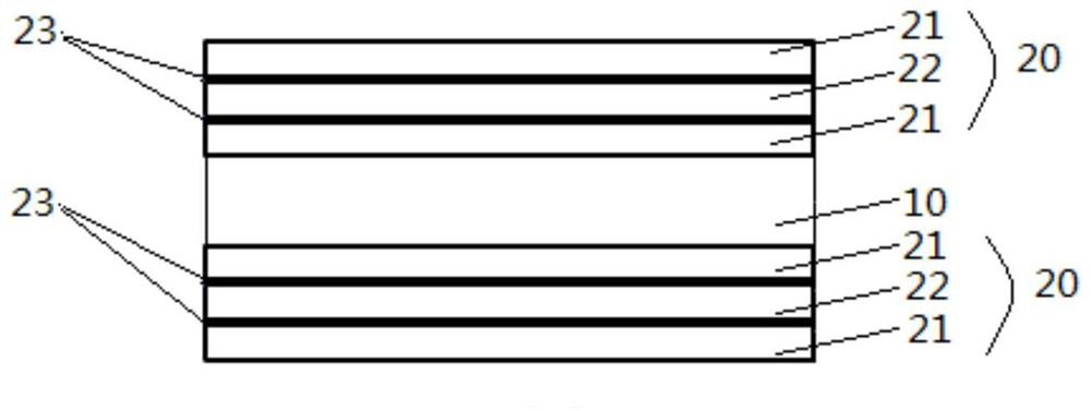
[0051] In another typical embodiment of the present application, a method for preparing any of the above-mentioned visible light cut-off films is provided, the preparation method comprising: Step S1, setting a high refractive index material layer 21 on the substrate layer 10; Step S2 , setting the matching material layer 22 on the high refractive index material layer 21; and optionally repeating step S3 one or more times, setting the high refractive index material layer 21 on the matching material layer 22, and setting Matching material layer 22 .
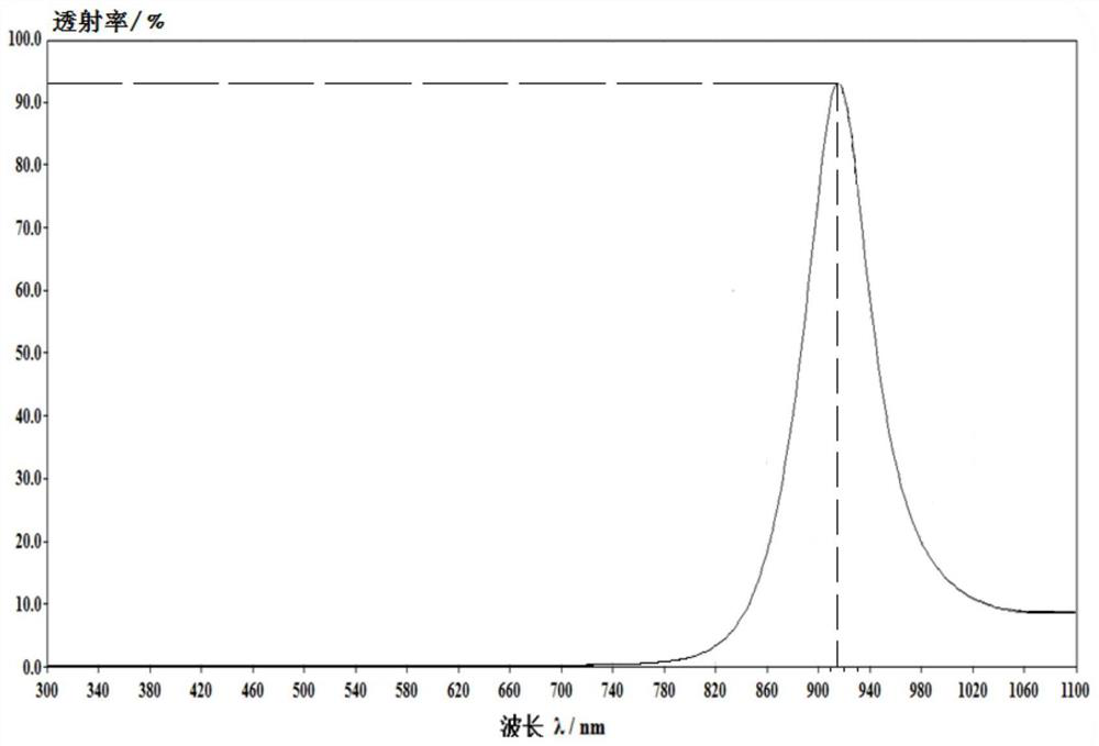
[0052] Since the high refractive index material layer 21 of the present application has a refractive index of 3 to 5.5, it has good absorptivity to ultraviolet light and visible light; and it is matched with the matching material layer 22 to form a structural water Layer 23, the refractive index of the structured water layer 23 is similar to that of water and is about 1.3, so it can form a thin film interference with the high refra...
Embodiment 1
[0063] The film structure of the visible light cut-off film in this embodiment is Air|1.376L1.795H|Sub|5.003H0.236L|Air, wherein: Sub is the substrate layer, Air is air; H is the α-hydrogenated amorphous silicon layer, and the refraction The refractive index is 4.306; L is a silicon dioxide layer with a refractive index of 1.470, which can be referred to figure 1 .
[0064] The above-mentioned visible light cut-off film was prepared by vacuum magnetron sputtering method:
[0065] (1) Forming a hydrogenated amorphous silicon layer on the substrate
[0066] The substrate is strictly cleaned before use: soak in standard washing solution (saturated potassium permanganate solution of sulfuric acid) for 24 hours; then, ultrasonically clean with toluene, acetone and ethanol for 15 minutes respectively, and rinse repeatedly with deionized water; finally , and store the cleaned substrate in analytically pure ethanol in the dark until use.
[0067] Using the TXZ500-2 radio frequency ...
Embodiment 2
[0073] The above-mentioned visible light cut-off film was prepared by PECVD method:
[0074] (1) Forming a hydrogenated amorphous silicon layer on the substrate
[0075] Using 4% silane diluted with high-concentration hydrogen as the reaction gas source of the plasma chemical vapor deposition (PECVD) process, when the vacuum reaches 1.0×10 -4 At Pa, the film was deposited on a K9 glass substrate with a thickness of 1.1 mm, the frequency of the radio frequency power supply was 13.56 MHz, and the gas flow rate was 20 sccm during the reaction. Amorphous silicon thin film at lower gas pressure (10Pa) and power density (30mW / cm 2 ) deposition, the RF electrode temperature was kept constant at 150°C, and the substrate temperature was controlled at 200°C. The RM2000 laser Raman spectrometer used in the measurement was used to observe the hydrogenated amorphous silicon layer, and the SE850 spectroscopic ellipsometer was used to measure its thickness.
[0076] (2) Forming a silicon ...
PUM
| Property | Measurement | Unit |
|---|---|---|
| thickness | aaaaa | aaaaa |
| thickness | aaaaa | aaaaa |
| thickness | aaaaa | aaaaa |
Abstract
Description
Claims
Application Information
 - R&D
- Intellectual Property
- Life Sciences
- Materials
- Tech Scout
- Unparalleled Data Quality
- Higher Quality Content
- 60% Fewer Hallucinations
Browse by: Latest US Patents, China's latest patents, Technical Efficacy Thesaurus, Application Domain, Technology Topic, Popular Technical Reports.
© 2025 PatSnap. All rights reserved.Legal|Privacy policy|Modern Slavery Act Transparency Statement|Sitemap|About US| Contact US: help@patsnap.com


