
Eureka
For R&D, Eureka makes reading and utilizing patents & technical documents easy.
Eureka AIR
Designed for self-driven R&D workflows. Generate viable solutions, solve complex R&D challenges, empower your innovation with AI.

Eureka Materials
Designed for material experts only. Revolutionize your material R&D, from search, analyze, to developing new materials.

TechResearch
Generate reliable direction feasibility study reports for your R&D in just a few steps.

TechSeek
Discover and master advanced knowledge NOW. Basics, ideas, possibilities, all at once.

TechMind
As an expert in R&D Theories, TechMind can generates customized viable solutions instantly.

TechRisk
Analyze your overall solution with one click, know your potential R&D risks in advance.

TechMonitor
Get weekly tech updates, stay abreast of the latest tech innovations and key insights.
Space omnidirectional obstacle avoidance method and system for an aircraft
A technology of flight control system and aircraft, applied in the direction of control/regulation system, instrument, non-electric variable control, etc., can solve limited and insufficient safety problems, achieve the effect of reducing hardware cost, processing time and energy consumption
- Summary
- Abstract
- Description
- Claims
- Application Information
AI Technical Summary
Problems solved by technology
Method used
Image

Examples
Embodiment 1
[0044] Embodiment 1 A space omnidirectional obstacle avoidance system for aircraft
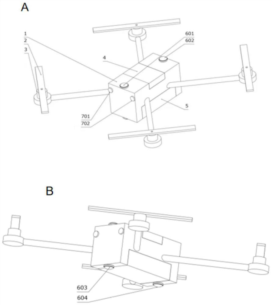
[0045] as attached figure 1 As shown, the obstacle avoidance system includes a quadrotor unmanned aerial vehicle, and the aircraft includes a fuselage 1, four propellers 2, four motors 3, a camera, a flight control system 4 and a battery system 5.
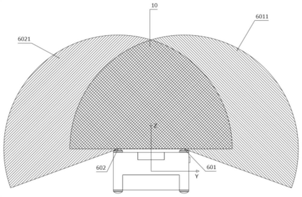
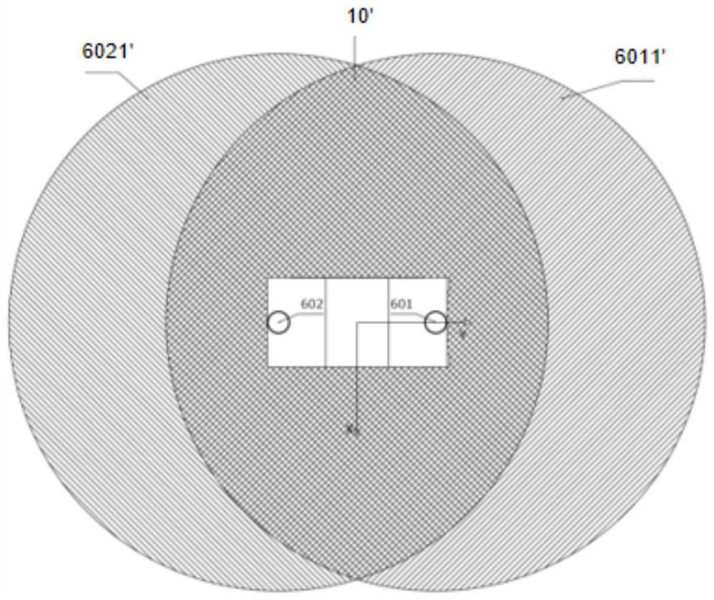
[0046] One of the installation methods is: three groups of cameras are installed on the fuselage, the first group of cameras 601 and 602 are respectively installed at the position above the nose and the position above the tail; the second group of cameras 603 and 604 are respectively installed at The bottom of the fuselage is completely symmetrical to the installation position of the camera above the fuselage; the third group of cameras 701 and 702 are installed directly in front of the nose respectively.
[0047] Another installation method is: the first group of cameras 601 and 602 are respectively installed on the position above the nose and th...
Embodiment 2
[0055] Embodiment 2 A method for omnidirectional obstacle avoidance in aircraft space
[0056] Including the following steps:
[0057] Step 1, collect a group of images of fisheye binocular cameras;
[0058] Step 2. Input the binocular image collected in step 1 into the deep learning network model for calculating depth, and output the predicted depth map
[0059] Step 3, input the binocular image collected in step 1 to the depth stereo matching calculation module, and output the real depth map d(x, y);
[0060] Step 4. Calculate the matching loss Where W is the image width, H is the image height, and iteratively optimizes the deep learning network model to minimize the matching loss;
[0061] Step 5. Repeat steps 1 to 4 until the matching loss loss is less than the threshold ε;
[0062] Step 6. According to the spatial relationship The predicted depth map output from step 1 Each point in is projected into the 3D space, and the 3D point cloud P is output;
[0063] S...
PUM
 Abstract
Description
Claims
Application Information
 - R&D Engineer
- R&D Manager
- IP Professional
- Industry Leading Data Capabilities
- Powerful AI technology
- Patent DNA Extraction
Browse by: Latest US Patents, China's latest patents, Technical Efficacy Thesaurus, Application Domain, Technology Topic, Popular Technical Reports.
© 2024 PatSnap. All rights reserved.Legal|Privacy policy|Modern Slavery Act Transparency Statement|Sitemap|About US| Contact US: help@patsnap.com