


Quick Research
Generate reliable direction feasibility study reports for your R&D in just a few steps.

Technical Q&A
Discover and master advanced knowledge NOW. Basics, ideas, possibilities, all at once.

Find Solutions
As an expert in R&D theories, this can generate solutions to your technical problems instantly.

Evaluate Feasibility
Analyze your overall solution with one click, know your potential R&D risks in advance.

Monitor Landscape
Get weekly tech updates, stay abreast of the latest tech innovations and key insights.
Cervical conization operation instrument capable of adjusting depth and rotating speed and use method
A surgical and cervical technology, applied in anatomical instruments, obstetrics and gynecological instruments, applications, etc., can solve the problems of patient injury, inconvenient control of the cutting depth and rotation speed of the scalpel, and avoid contamination and excessive cutting depth , the effect of relieving pain
- Summary
- Abstract
- Description
- Claims
- Application Information
AI Technical Summary
Problems solved by technology
Method used
Image

Examples
Embodiment 1
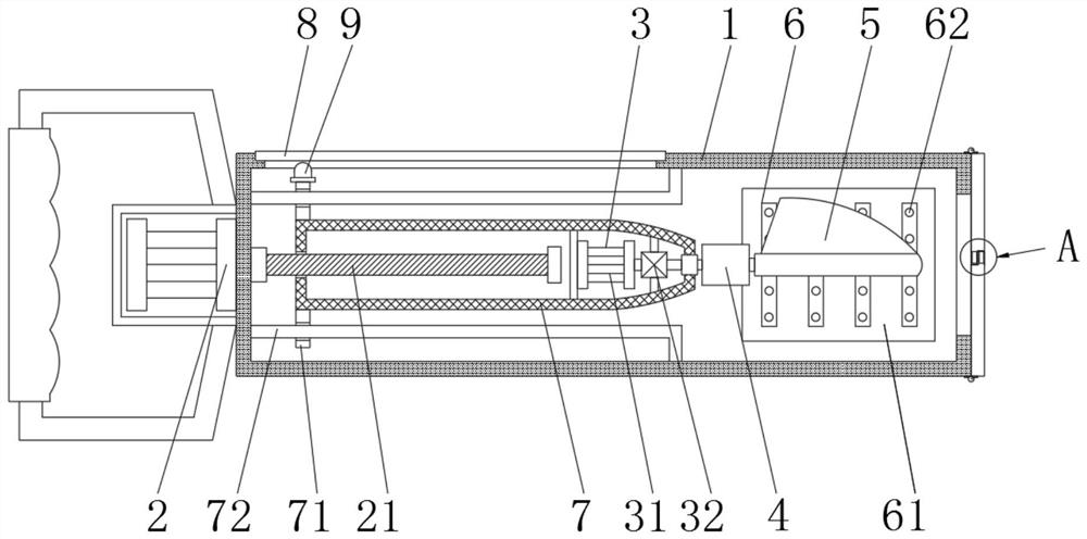
[0036] see Figure 1-7 , the present embodiment provides an instrument for cervical conization surgery capable of adjusting depth and rotational speed and a method of use thereof, comprising a circular sleeve 1 and a first motor 2, the outer side of the left end of the circular sleeve 1 is fixedly connected with the first motor 2, The output shaft of the first motor 2 runs through the left side wall of the circular sleeve 1 and is fixedly connected with a threaded rod 21. The threaded rod 21 is threadedly connected with the installation sleeve 7. After the first motor 2 is energized, the threaded rod 21 can be driven to rotate. When the rod 21 rotates, the mounting sleeve 7 can be driven to move left and right, so that the cutter 5 can be adjusted during the operation, and then the extension length of the cutter 5 can be adjusted according to the operation requirements, so as to facilitate the control of the cutting depth during the operation.
[0037] Such as figure 1 with ...
Embodiment 2
[0050] refer to Figure 8 , the difference between embodiment 2 and embodiment 1 is:
[0051] Rotate between the interior front and rear side walls of the installation groove is connected with pole 55, the lower end of pole 55 is fixedly connected with limit ball 57, the upper end of pole 55 is fixedly connected with shifting block 56, and the shifting block 56 just can make support When the rod 55 rotates, the position of the limit ball 57 can be adjusted so that it can be moved out of the draw-in groove 41 , and the connecting piece 51 can be taken out from the inside of the fixing piece 4 .
[0052] A spring is installed between the upper end of the pole 55 and the side wall of the mounting groove, and when the limit ball 57 is located in the draw-in groove 41, the spring is in a compressed state, and affected by the rebound force of the spring itself, the upper end of the pole 55 will Close to the inner wall of the installation groove, the limit ball 57 will be firmly cla...
PUM
 Abstract
Description
Claims
Application Information
 - R&D Engineer
- R&D Manager
- IP Professional
- Industry Leading Data Capabilities
- Powerful AI technology
- Patent DNA Extraction
Browse by: Latest US Patents, China's latest patents, Technical Efficacy Thesaurus, Application Domain, Technology Topic, Popular Technical Reports.
© 2024 PatSnap. All rights reserved.Legal|Privacy policy|Modern Slavery Act Transparency Statement|Sitemap|About US| Contact US: help@patsnap.com