
Automatic sand core production device

A production device and sand core technology, which is applied to casting molding equipment, parts of molding machines, metal processing equipment, etc., can solve the problems affecting the quality of castings, many types of molds, and sand core falling off, so as to improve the quality of sand cores and reduce Safety risk, effect of improving airtightness

Pending Publication Date: 2021-07-13
WUXI XINAN ALUMINUM TECH
View PDF7 Cites 1 Cited by
  • Summary
  • Abstract
  • Description
  • Claims
  • Application Information

AI Technical Summary

Problems solved by technology

[0002] In the current foundry, due to the limited investment in equipment, the shell core machine has a single specification and a limited number, but there are many types of molds and a large number, so the sand shooting system of the equipment cannot meet the requirements for frequent switching of multiple molds and multiple molds. Causes falling sand during the sand shooting process, which affects the quality of castings
In addition, when manufacturing different sand cores, it is necessary to switch the sand shooting system frequently, which increases the debugging time and the labor intensity of the operator; in addition, the traditional sand shooting board uses a sticker board to avoid hard contact with the mold surface, and the cardboard is easily damaged during the contact process with the mold , resulting in poor sealing and affecting the quality of castings
A sand shooting system needs to share the left and right molds. Due to the different requirements of the two molds, it is impossible to share one sand injection port. Multiple sand injection ports need to be opened. During the sand shooting process, the redundant sand injection ports have pressure relief. , leading to poor sealing and affecting the quality of castings
[0003] Moreover, in the existing sand core production equipment, the manufactured sand cores are generally taken manually. Due to the high temperature of the sand cores, there is a risk of burns to people, which is likely to cause production safety accidents.
A small number of devices use robotic gripping. Robotic gripping generally adopts hard connections, and the debugging period before production is long. The gripping force of the jaws is not easy to control during the actual gripping process. If the force is too small, it may easily cause the risk of sand core falling off. However, if the force is too large, there is a risk of crushing the sand core

Method used


Image

  • Automatic sand core production device
  • Automatic sand core production device
  • Automatic sand core production device

Examples


Embodiment Construction

[0022] In order to deepen the understanding of the present invention, the present invention will be further described below in conjunction with the accompanying drawings. This embodiment is only used to explain the present invention, and does not constitute a limitation to the protection scope of the present invention.

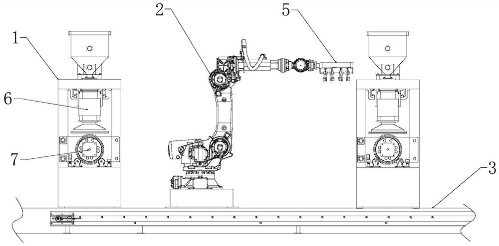
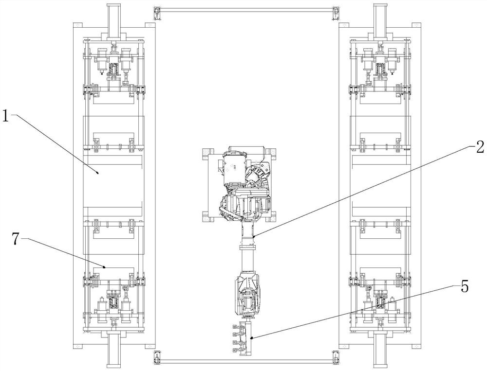
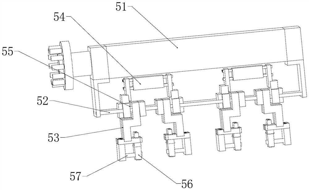
[0023] Figure 1-7 It shows an automatic sand core production device, including a core making machine 1, a mechanical arm 2 and a conveyor belt 3. After the core making machine 1 produces a sand core 4, the floating manipulator gripper arm 2 can transfer the sand core 4 to the conveyor belt. On the belt 3, the front end of the mechanical arm 2 is connected with a floating manipulator gripper 5, the floating manipulator gripper 5 includes a rotating shaft 51, a sliding bar 52, and a gripping jaw 53, the rotating shaft 51 is connected with the mechanical arm 2, and the sliding bar 52 is fixedly connected On the rotating shaft 51, the jaws 53 are installed on the...


PUM


Abstract

An automatic sand core production device comprises a core making machine, a mechanical arm and a conveying belt; the front end of the mechanical arm is connected with a floating manipulator clamping jaw; the floating manipulator clamping jaw comprises a rotating shaft, a sliding rod and clamping jaws; the rotating shaft is connected with the mechanical arm; the sliding rod is fixedly connected to the rotating shaft; the clamping jaws are arranged on the sliding rod in a penetrating mode; an air cylinder is connected between the two clamping jaws; the air cylinder can drive the clamping jaws to move along the sliding rod to be opened and closed to grab the sand core; and as a floating spring is further arranged at the joint of the air cylinder and the clamping jaws, the floating spring is compressed in the process that the clamping jaws clamp the sand core, so that the buffering effect is achieved. Due to the arrangement of a sand shooting plate, sand is prevented from falling to a mold cavity surface before sand shooting, and the quality of the sand core is improved; As professional vulcanized fluororubber is additionally arranged at the bottom of the sand shooting plate, hard contact between the sand shooting plate and the surface of a mold is avoided, the sealing performance is improved, and the service life is long; and as a plurality of sand shooting openings are formed in the sand shooting plate at the same time, the sand shooting openings in different positions are opened according to different molds, so that the requirements of the different molds can be met.

Description

technical field [0001] The invention relates to the technical field of molding sand manufacturing equipment, in particular to an automatic sand core production device. Background technique [0002] In the current foundry, due to the limited investment in equipment, the shell core machine has a single specification and a limited number, but there are many types of molds and a large number, so the sand shooting system of the equipment cannot meet the requirements for frequent switching of multiple molds and multiple molds. It causes sand falling during the sand shooting process, which affects the quality of castings. In addition, when manufacturing different sand cores, it is necessary to switch the sand shooting system frequently, which increases the debugging time and the labor intensity of the operator; in addition, the traditional sand shooting board uses a sticker board to avoid hard contact with the mold surface, and the cardboard is easily damaged during the contact pro...

Claims


Application Information

Patent Timeline
Patent Type & Authority Applications(China)
IPC IPC(8): B22C15/24B22C19/00
CPCB22C15/24B22C19/00
Inventor 杨忠
Owner WUXI XINAN ALUMINUM TECH
Learn More