Three-dimensional integrated anaerobic fermentation equipment

An anaerobic fermentation, integrated technology, applied in the direction of organic fertilizer equipment, preparation and application of organic fertilizer, can solve the problem of inability to discharge, avoid accumulation and blockage, and ensure the effect of closure

Inactive Publication Date: 2021-07-13
广州市至佳实业有限公司
View PDF0 Cites 1 Cited by
  • Summary
  • Abstract
  • Description
  • Claims
  • Application Information

AI Technical Summary

Problems solved by technology

[0005] In order to solve the above-mentioned technology, when the equipment is used to ferment the straw, because part of the straw is relatively long and light in weight, when the fermented straw fertilizer is discharged together with the water flow, it will be locked at the corner of the equipment pipeline. , but can not be effectively discharged with the water flow, and then make the slender straw pile up at the bend of the pipe

Method used


Image

  • Three-dimensional integrated anaerobic fermentation equipment
  • Three-dimensional integrated anaerobic fermentation equipment
  • Three-dimensional integrated anaerobic fermentation equipment

Examples


Embodiment 1

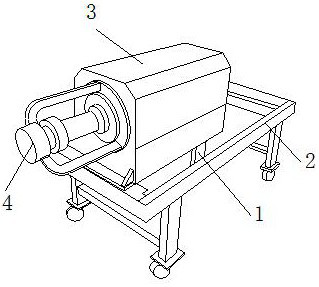
[0029] as attached figure 1 to attach Image 6 Shown:

[0030] The present invention provides a three-dimensional integrated anaerobic fermentation equipment, the structure of which includes a drainage pipe 1, a bracket 2, a fermentation tank 3, and a heating rotating rod 4, the drainage pipe 1 is embedded and installed on the lower surface of the fermentation tank 3, The bracket 2 is inlaid and engaged with the fermenter 3, and the left end surface of the fermenter 3 is inlaid and engaged with a heating rotating rod 4, and the heating rotating rod 4 is located above the left side of the drain pipe 1; The drainage pipe 1 includes a collection device 11, a collection pool 12, a hollow pipe 13, and a nozzle cover 14. The collection device 11 is inlaid and fitted on the inner end surface of the hollow pipe 13, and the collection pool 12 is located on the front side of the collection device 11. Above, the inner end surface on the right side of the hollow tube 13 is nested with a...

Embodiment 2

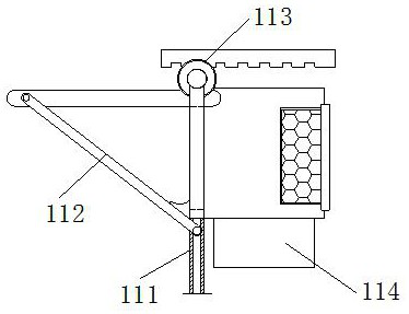
[0038] as attached Figure 7 To attach Figure 9 Shown:

[0039] Wherein, the linkage device 113 includes a latching rod 131, a closing plate 132, and a latching gear 133. The latching rod 131 is inlaid and fitted directly below the latching gear 133, and the closing plate 132 is located on the latching rod 131. Directly above, the outer end surface of the locking gear 133 is inlaid and engaged with the closing plate 132. The left end surface of the closing plate 132 is made of rubber. When the locking gear 131 and the locking gear 133 are driven to the left , the closing plate 132 can be pressed against the inner wall of the hollow tube 13 to close the end surface.

[0040] Wherein, the closing plate 132 includes an inlaid plate 321, an embedding block 322, an extruding plate 323, and a wrapping ring 324. The lower end surface on the left side of the inlaying plate 321 is embedded with an embedding block 322, and the embedding block 322 The inlay is arranged directly below...


PUM


Abstract

The invention discloses three-dimensional integrated anaerobic fermentation equipment which structurally comprises a drainage pipe, a support, a fermentation tank and a heating rotating rod; the drainage pipe is fixedly embedded in the lower end surface of the fermentation tank, the support is connected with the fermentation tank in an embedded and clamped mode, the heating rotating rod is embedded and clamped in the left side end face of the fermentation tank, and the heating rotating rod is located above the left side of the drainage pipe; when straw collected at the end face of a filter screen is gradually increased, the distance between the end faces of the filter screen is gradually shortened, the impact force of water flow is increased, under continuous impact of the water flow, the filter screen can gradually slide rightwards in a second sliding rail through clamping of a movable shaft and a first sliding rail, and the movable shaft can slowly slide downwards in the first sliding rail; and meanwhile, embedded shafts on the left side and the right side are pulled, so that when the filter screen swings, the straw attached to the surface of the filter screen can be scraped through attachment of swing blocks, the straw is discharged to a storage box, and accumulation and blockage caused by excessive straw are avoided.

Description

technical field [0001] The invention belongs to the field of anaerobic fermentation equipment, and more specifically relates to a three-dimensionally integrated anaerobic fermentation equipment. Background technique [0002] The three-dimensional integrated anaerobic fermentation equipment is a kind of equipment that puts anaerobic bacteria in the reaction tank, then pours water and the fermented matter into the closed equipment, and then through continuous intermittent heating and rolling, the fermented matter can receive effective And uniform fermentation effect equipment. [0003] Based on the inventors' findings above, the existing methods mainly have the following disadvantages. For example, when using equipment to ferment straw, some straws are relatively slender and light in weight, so that the fermented straw fertilizer and water flow together When it is discharged outside, it will be locked at the corner of the equipment pipe, and cannot be effectively discharged w...

Claims


Application Information

Patent Timeline
Patent Type & Authority Applications(China)
IPC IPC(8): C05F17/95C05F17/964C05F17/20C05F17/986C05F17/60C05F11/00
CPCC05F11/00C05F17/20C05F17/60C05F17/95C05F17/964C05F17/986Y02W30/40
Inventor 黄有小
Owner 广州市至佳实业有限公司
Why Eureka
Try Eureka