Antenna housing electrical performance test system and method for simulating phased-array antenna

A phased array antenna and testing system technology, applied in radiation unit housing, special data processing applications, design optimization/simulation, etc., can solve the problems of numerous components, high cost, complex control system, etc. low cost effect

Active Publication Date: 2021-07-13
CHINA ELECTRONIS TECH INSTR CO LTD
View PDF9 Cites 3 Cited by
  • Summary
  • Abstract
  • Description
  • Claims
  • Application Information

AI Technical Summary

Problems solved by technology

However, the radome electrical performance test system of this phased array antenna has many components, the control system is complicated, and its cost is very expensive.

Method used


Image

  • Antenna housing electrical performance test system and method for simulating phased-array antenna
  • Antenna housing electrical performance test system and method for simulating phased-array antenna
  • Antenna housing electrical performance test system and method for simulating phased-array antenna

Examples


Embodiment 1

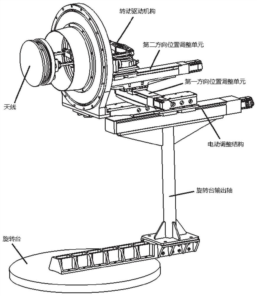
[0024] In one or more embodiments, a radome electrical performance test system for simulating a phased array antenna is disclosed, referring to figure 1 ,include:

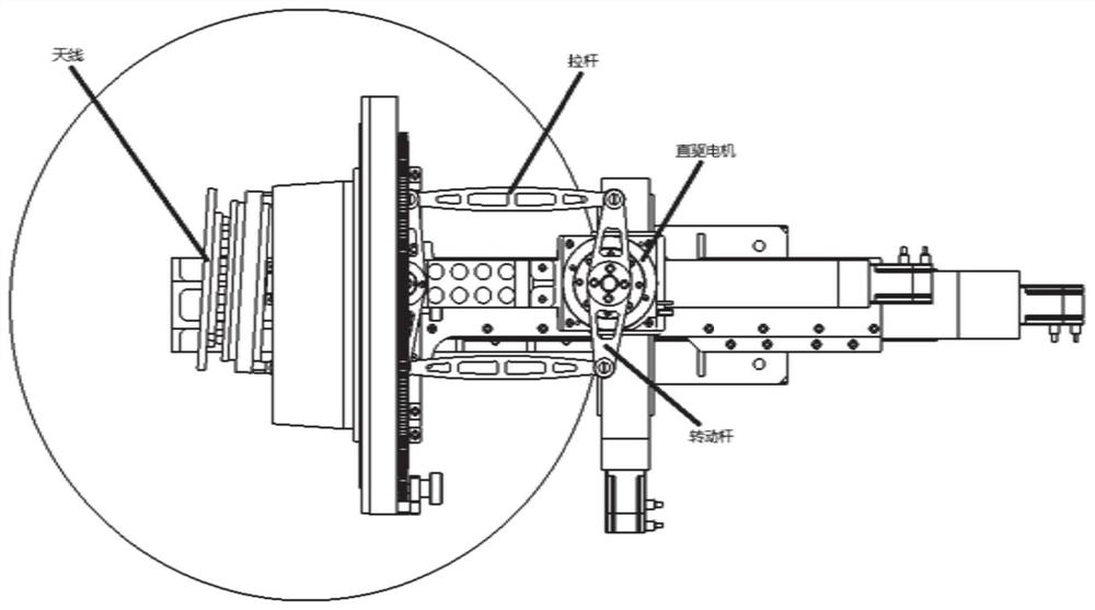
[0025] The base is provided with a rotary platform for adjusting the horizontal rotation angle of the radome, the output shaft of the rotary platform is connected to the position adjustment mechanism, and the position adjustment mechanism is connected to the antenna through the rotation drive mechanism;

[0026] The position adjustment mechanism includes a position adjustment unit in the first direction and a position adjustment unit in the second direction. The position adjustment unit in the first direction can drive the receiving antenna to move left and right, thereby changing the position of the center point of the antenna in the left and right directions; the position adjustment unit in the second direction can drive the receiving antenna to move left and right. The receiving antenna moves back and forth, the...

Embodiment 2

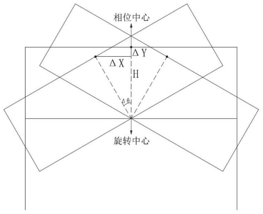
[0039] In one or more embodiments, a method for testing the electrical performance of a radome simulating a phased array antenna is disclosed, including: adjusting the position of the common antenna so that the phase center position of the antenna remains unchanged during the rotation of the antenna, To simulate the phased array antenna, to test the electrical performance of the radome at different angles.

[0040] For a specific method of adjusting the position of the common antenna to keep the phase center position of the antenna unchanged, refer to the determination process of the left-right offset and front-back offset given in Embodiment 1.

[0041] In the specific test process, first initialize the position of the electric adjustment structure, the first direction position adjustment unit and the second direction position adjustment unit so that the rotation center of the azimuth axis of the receiving antenna is aligned with the rotation center of the azimuth axis of the ...


PUM


Abstract

The invention discloses an antenna housing electrical performance test system and method for simulating a phased-array antenna, and the system comprises: a base which is provided with a rotating table used for adjusting the horizontal rotation angle of an antenna housing, wherein an output shaft of the rotating table is connected with a position adjustment mechanism, and the position adjustment mechanism is connected with an antenna through a rotation driving mechanism; and a position adjusting mechanism, wherein the position adjusting mechanism comprises a first direction position adjusting unit and a second direction position adjusting unit, and the position of the antenna is adjusted through the first direction position adjusting unit and the second direction position adjusting unit, so that the rotation center of the azimuth axis of the rotary table and the rotation center of the azimuth axis of the antenna are on the same straight line, and the phase center position of the antenna is not changed in the rotating process. A common antenna is adopted, and the phase center position of the antenna is ensured to be unchanged through two-axis adjustment, so that a phased-array antenna is simulated to carry out an antenna housing electrical performance test; and the test system is simple and low in cost, and can be compatible with the radome test of the non-phased-array antenna.

Description

technical field [0001] The invention relates to the technical field of radome electrical performance testing, in particular to a radome electrical performance testing system and method for simulating a phased array antenna. Background technique [0002] The statements in this section merely provide background information related to the present invention and do not necessarily constitute prior art. [0003] With the rapid development of electronic technology, applications such as airborne early warning radar, wireless communication, and radio frequency identification have higher and higher requirements for antennas, especially for flexible control of antenna patterns. The flexible control of the beam and fast scanning of the phased array antenna are well suited to this requirement. The radome is an important part of the missile antenna system, and it is also a common carrier of the phased array antenna in the aircraft. The radome protects the seeker antenna from the interfe...

Claims


Application Information

Patent Timeline
IPC IPC(8): G06F30/20H01Q1/42
CPCG06F30/20H01Q1/42
Inventor 张升华王金榜陈安涛颜振曹桂财
Owner CHINA ELECTRONIS TECH INSTR CO LTD
Why Eureka
Try Eureka