
Superfine column crystal high-temperature alloy blade and laser directional solidification preparation method thereof

A high-temperature alloy and directional solidification technology, applied in metal processing equipment, manufacturing tools, casting equipment, etc., can solve problems affecting the performance of ultra-fine directional columnar crystal products, columnar crystals deviate from the center position, and restrict the application of laser directional solidification technology. Achieve the effect of reducing disorderly oriented grains, reducing porosity, and reducing morphological changes

Active Publication Date: 2021-07-16
北京煜鼎增材制造研究院有限公司
View PDF13 Cites 3 Cited by
  • Summary
  • Abstract
  • Description
  • Claims
  • Application Information

AI Technical Summary

Problems solved by technology

[0005] However, during the layer-by-layer deposition process of laser directional solidification, due to the influence of the surface tension of the molten pool liquid and the strong internal convection, the columnar crystals may deviate from the center position.
Although there have been many researches and achievements on the directional solidification of columnar crystals, no very effective solutions have been proposed for the above problems, which seriously affects the product performance of ultra-fine directional columnar crystals prepared by laser directional solidification, thus restricting the laser Application of Directional Solidification Technology in the Preparation of Ultrafine Columnar Superalloy Blades

Method used


Image

  • Superfine column crystal high-temperature alloy blade and laser directional solidification preparation method thereof
  • Superfine column crystal high-temperature alloy blade and laser directional solidification preparation method thereof
  • Superfine column crystal high-temperature alloy blade and laser directional solidification preparation method thereof

Examples


Embodiment 1

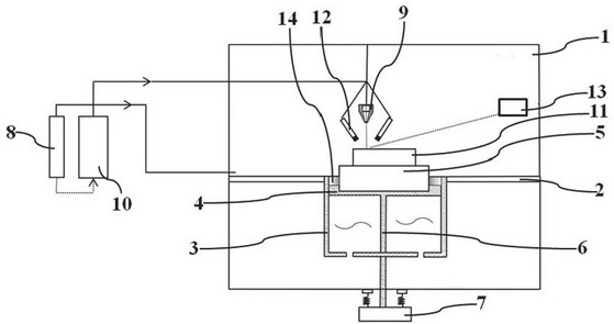
[0033] A special device for implementing the preparation method of laser directional solidification. The present invention implements the preparation method of laser directional solidification in the special device developed by the inventor himself, such as figure 1 As shown, the special device includes a processing chamber 1, a partition 2 is arranged in the middle of the processing chamber 1, an opening is arranged in the middle of the partition and a water-cooled box 3 is arranged downward along the opening, and a water-cooled copper plate 4 is arranged on the top of the water-cooled box 3 The bottom of the water-cooled box 3 is provided with a channel so that the cooling medium can enter the space below the water-cooled copper plate 4 of the water-cooled box 3. The top of the water-cooled copper plate 4 is used to place the directional solidification substrate 5, and the bottom surface of the water-cooled copper plate 4 is fixedly connected with the upper and lower driving ...


PUM

PropertyMeasurementUnit
Diameteraaaaaaaaaa

Abstract

The invention discloses a laser directional solidification preparation method for a superfine column crystal high-temperature alloy blade. The method specifically comprises the following steps that (1) a substrate is placed on a water-cooling copper plate, the <001> orientation of the substrate is made to be perpendicular to the water-cooling copper plate, the water-cooling copper plate is movably arranged in a water-cooling box, and the space below the water-cooling copper plate of the water-cooling box and the periphery of the water-cooling box are filled with cooling water; and (2) directional solidification deposition is conducted in a layer-by-layer scanning mode through laser to prepare a columnar crystal, in the scanning process, the scanning mode that in-layer lap joint is not conducted and inter-layer lap joint is conducted is adopted, and the water-cooling copper plate moves downwards along the inner wall of the water-cooling box after scanning of each layer is completed. According to the laser directional solidification preparation method, a stable ultrahigh directional temperature gradient can be maintained in a large range, and the overall orientation of the whole columnar crystal is kept.

Description

technical field [0001] The invention relates to the technical field of laser directional solidification, in particular to an ultrafine columnar superalloy blade and a preparation method thereof by laser directional solidification. Background technique [0002] The performance of engine blades is one of the important factors restricting the performance level of aeroengines, and it is usually required that the blades can work stably for a long time under high temperature and high pressure. However, the grain boundary perpendicular to the stress axis becomes the weak part of the ordinary cast superalloy, which leads to creep fracture of the superalloy at high temperature with a small amount of deformation. The directional crystallization vane eliminates the transverse grain boundaries that are sensitive to voids and cracks, and makes all grain boundaries parallel to the stress axis, thereby improving the performance of the alloy. [0003] Traditional casting directional solidi...

Claims


Application Information

Patent Timeline
IPC IPC(8): B22D27/04B22D46/00B22C9/22
CPCB22C9/22B22D27/045B22D46/00
Inventor 不公告发明人
Owner 北京煜鼎增材制造研究院有限公司
Learn More