Unlock instant, AI-driven research and patent intelligence for your innovation.

Multi-axis numerical control machine tool

A CNC machine tool and bed technology, which is applied to metal processing machinery parts, large fixed members, clamping and other directions, can solve the problems of inability to go upstairs, difficult processing, and large linkage range of linear axes, and achieves reduction of overall width and size, The effect of reducing machining geometric errors and improving the efficiency of multi-axis linkage

Pending Publication Date: 2021-07-16
BEIJING JINGDIAO GRP CO LTD
View PDF0 Cites 1 Cited by
  • Summary
  • Abstract
  • Description
  • Claims
  • Application Information

AI Technical Summary

Problems solved by technology

[0002] There are a number of typical industries in the market, whose product features are small, precise and complex, such as small precision core molds, watch cases, movements, dental implant abutments, precious metal jewelry, etc. These products have a great impact on processing accuracy and surface effects. It has high requirements on processing efficiency and processing difficulty, and has strict requirements on the area and weight of processing equipment
Existing miniaturized processing equipment has problems such as poor rigidity and low processing accuracy, and most of them are mainly three-axis CNC machine tools, which are difficult to achieve high-precision and high-efficiency processing of complex products; although multi-axis CNC machine tools can achieve high precision for complex products. Precision machining, but the existing multi-axis CNC machine tools are generally heavy and have problems such as large footprint, low space utilization rate, and inability to go upstairs, which makes it difficult to meet the requirements of the above-mentioned products for the processing equipment footprint and application site; The existing multi-axis processing equipment still has problems such as low tool change efficiency and large linear axis linkage range due to the influence of structural layout, which affects the improvement of processing efficiency.

Method used


Image

  • Multi-axis numerical control machine tool
  • Multi-axis numerical control machine tool
  • Multi-axis numerical control machine tool

Examples


Embodiment Construction

[0022] The present invention will be further described in detail below in conjunction with the accompanying drawings and specific embodiments.

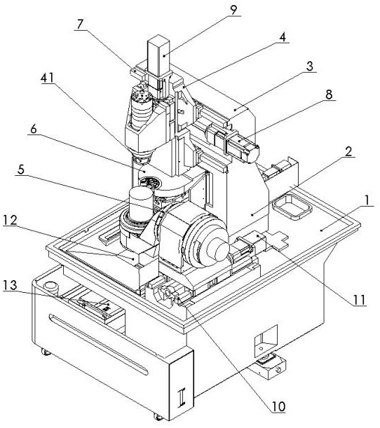
[0023] Such as figure 1 As shown, a multi-axis CNC machine tool of the present invention includes a bed 1 , a column 2 , a beam 3 , a head assembly 4 , a cantilever turntable 5 , and a tool magazine 6 . The column 2 and the crossbeam 3 form a gantry structure and are installed on the rear end of the bed 1. The crossbeam 3 is provided with an X-guiding rail 7, and the head assembly 4 slides on the X-guiding rail 7. Move in X direction. The head assembly 4 is provided with a main shaft 41 which can reciprocate along the Z direction under the action of the Z-axis drive 9 . The right side of the bed 1 is provided with a Y guide rail 10 , and the left side of the bed 1 is provided with a chip discharge port 12 . The Y-guiding rail 10 is located in front of the beam 3 , and the cantilever turntable 5 slides on the Y-guiding rail 10 , and...


PUM


Abstract

The invention belongs to the field of numerical control machining, and particularly relates to a multi-axis numerical control machine tool. The multi-axis numerical control machine tool is compact in structure, high in space utilization rate, small in occupied area, low in weight, high in tool changing efficiency and small in linear axis linkage range so as to achieve high-precision and high-efficiency machining of small precise complex products. The multi-axis numerical control machine tool comprises a lathe bed, a stand column, a cross beam, a tool magazine and a cantilever rotary table, wherein the cross beam and the stand column form a gantry structure to be mounted at the rear end of the lathe bed; the tool magazine and the cantilever rotary table are both mounted on the lathe bed; the cantilever rotary table is positioned in front of the cross beam and can move forwards and backwards along the lathe bed; and the tool magazine is arranged below the cross beam and can be pushed out of the cross beam.

Description

technical field [0001] The invention belongs to the field of numerical control machining, in particular to a multi-axis numerical control machine tool. Background technique [0002] There are a number of typical industries in the market, whose product features are small, precise and complex, such as small precision core molds, watch cases, movements, dental implant abutments, precious metal jewelry, etc. These products have a great impact on processing accuracy and surface effects. It requires high processing efficiency and high processing difficulty, and has strict requirements on the footprint and weight of processing equipment. Existing miniaturized processing equipment has problems such as poor rigidity and low processing accuracy, and most of them are mainly three-axis CNC machine tools, which are difficult to achieve high-precision and high-efficiency processing of complex products; although multi-axis CNC machine tools can achieve high precision for complex products. ...

Claims


Application Information

Patent Timeline
Patent Type & Authority Applications(China)
IPC IPC(8): B23Q1/01B23Q1/26B23Q3/157
CPCB23Q1/01B23Q3/15724B23Q1/26B23Q3/15706
Inventor 王冰旭姚红民邓宇韩银平谷尚武王子义高鹏坡
Owner BEIJING JINGDIAO GRP CO LTD