Helicopter flight driving robot system

A robot system and driving robot technology, applied in the field of helicopter flying and driving robot system, can solve the problems of poor adaptability, great difference, working space, and control accuracy requirements and response speed requirements, etc., so as to reduce the transformation time and cost, meet the Control precision requirements, the effect of small structure weight

Active Publication Date: 2021-07-16
BEIHANG UNIV
View PDF10 Cites 2 Cited by
  • Summary
  • Abstract
  • Description
  • Claims
  • Application Information

AI Technical Summary

Problems solved by technology

However, car driving and aircraft manipulation are very different, and its design method cannot be directly applied to aircraft driving robots.
[0004] In addition, the driving robot actuator needs to be connected to the end of the aircraft control mechanism to realize flight driving. The working space, control accuracy requirements, and response speed requirements of each control mechanism of the helicopter are very different. Agencies prone to interference
Moreover, the layout of the cockpit and the position of the control mechanism of different types of helicopters are different. For the helicopter driving robot, the traditional integrated robot design method will make it impossible to expand and apply to other types of helicopters, and the adaptability is poor.

Method used


Image

  • Helicopter flight driving robot system
  • Helicopter flight driving robot system
  • Helicopter flight driving robot system

Examples


Embodiment Construction

[0042] In order to understand the above-mentioned purpose, features and advantages of the present invention more clearly, the present invention will be further described in detail below in conjunction with the accompanying drawings and specific embodiments. It should be noted that, in the case of no conflict, the embodiments of the present invention and the features in the embodiments can be combined with each other.

[0043] In the following description, many specific details are set forth in order to fully understand the present invention. However, the present invention can also be implemented in other ways different from those described here. Therefore, the protection scope of the present invention is not limited by the specific details disclosed below. EXAMPLE LIMITATIONS.

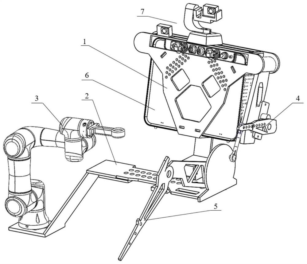
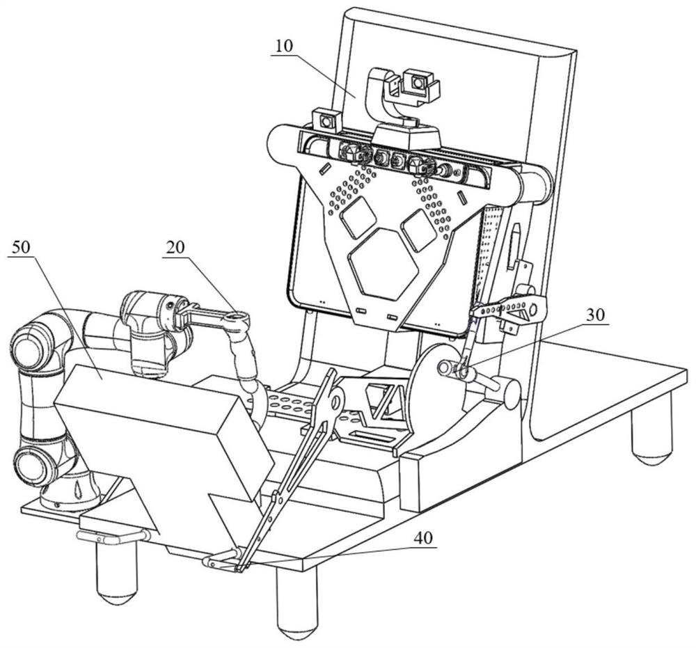
[0044] like Figure 1-2 As shown, the helicopter driving robot system provided by this embodiment includes a fuselage pylon 1, a fuselage bottom plate 2, a six-degree-of-freedom manipulator 3, a steer...


PUM


Abstract

The invention belongs to the technical field of aircrafts, and discloses a helicopter flight driving robot system. The helicopter flight driving robot system comprises a fuselage hanging frame, a fuselage bottom plate, a servo mechanism, a robot control box and a visual perception module, and the servo mechanism comprises a six-degree-of-freedom manipulator, a steering engine mechanical arm and a steering engine mechanical leg; the fuselage hanging frame is installed on a cockpit seat, and a space for containing the robot control box is formed in the fuselage hanging frame; the fuselage bottom plate is horizontally placed on the helicopter cockpit seat; the six-degree-of-freedom manipulator is used for controlling a helicopter steering column; the steering engine mechanical arm is used for controlling a helicopter collective pitch rod; the steering engine mechanical leg is used for controlling a helicopter rudder; and the visual perception module is used for monitoring the environment of a cockpit and the scene outside the cockpit. The robot system can be installed in the helicopter cockpit, the helicopter is independently piloted by connecting a robot executing mechanism and a helicopter control mechanism, and rapid switching between a manned mode and an unmanned mode of the helicopter can be achieved under the condition that the helicopter is not modified.

Description

technical field [0001] The invention belongs to the technical field of aircraft, in particular to a helicopter flight driving robot system. Background technique [0002] The existing unmanned methods of manned aircraft mainly modify the manned aircraft, dismantle the servo mechanism in the cockpit of the aircraft, connect the flight control computer to the aircraft control system, and realize the unmanned and automatic flight of the manned aircraft by modifying the control circuit of the aircraft. . This modification process is often irreversible, and the modification cost is very high. In contrast, using the method of aircraft driving a robot, installing the driving robot in the cockpit and controlling the aircraft control mechanism through the robot actuator to realize the robot driving manned aircraft can be achieved without modifying the original aircraft. The unmanned mode can be switched quickly and reversibly, which can not only drive the aircraft independently, but...

Claims


Application Information

Patent Timeline
Patent Type & Authority Applications(China)
IPC IPC(8): B25J9/08B25J9/16B25J11/00
CPCB25J11/00B25J9/16B25J9/1697B25J9/08
Inventor 李道春金子博向锦武孙毅
Owner BEIHANG UNIV
Why Eureka
Try Eureka