Eureka AIR delivers breakthrough ideas for toughest innovation challenges, trusted by R&D personnel around the world.

Ring main unit distribution automation reconstruction device

A technology for power distribution automation and automation devices, applied in switchgear, electrical components, etc., can solve the problems of the original outdoor box wasting civil construction and the environment, the power outage time increases economic losses, the original outdoor box waste and other problems, and achieves good practicability and universality. The effect of reducing the power outage time of the transformation and the small space occupied by the equipment

Active Publication Date: 2014-08-06
NATUS CHANGZHOU ELECTRIC +3
View PDF5 Cites 2 Cited by
  • Summary
  • Abstract
  • Description
  • Claims
  • Application Information

AI Technical Summary

Problems solved by technology

[0004] The main reason is that the secondary operating power required by the modified equipment is provided by the PT. However, the PT is too large to be directly installed in the original outdoor box. Therefore, it is necessary to install another outdoor box near the original outdoor box or directly install Replacing the original outdoor box will not only greatly increase the renovation time, but also cause waste of the original outdoor box or damage to civil engineering and the environment.
[0005] As far as we know, there is a renovation plan for outdoor ring network cabinets in Shanghai Pudong District. In order to install the PT cabinets and centralized DTU screens required for the power supply, all the original outdoor boxes will be replaced with new outdoor boxes during the renovation, resulting in waste of the original outdoor boxes. The replacement of the original outdoor box with a new outdoor box must be carried out in the factory, and returning to the factory for construction will inevitably increase the on-site power outage time, and the economic loss caused by the increased power outage time is even more immeasurable
[0006] In addition, the use of CT technology as a secondary power source has been used as early as a few years ago, and the most common application is passive comprehensive protection devices; However, since the initial application of this technology has always been biased towards low-power power consumption, the design of CT power-taking products for intelligent transformation that appeared in the later period also continued this trend. Design concept, taking the CT power-taking device designed by a power module manufacturer for the East China Power Grid as an example, the device needs to use a special CT customized by Dalian Second Transformer Factory, which is too large to be directly installed in the ring main unit. The primary current of a specific project can be customized, and since the device can only withstand a long-term load of 6W and a short-term load of 45W, a set of this CT power-taking device must be installed in each unit cabinet to meet the power consumption of secondary equipment. requirements, while the price of each device (including CT, power module and lithium battery) is about 2W, a set of 6-unit outdoor ring network cabinet, the equipment cost of the optical power part reaches 12W, which is obviously not practical
[0007] For the above renovation plan, since it is necessary to install PT, large CT or centralized DTU screen required for power supply, another outdoor box must be installed near the original outdoor box. Many switch stations, switching stations, outdoor ring stations, etc. Because the switchgear is limited by the original space, it is difficult to open up additional space to install the outdoor box, which has space constraints, high cost, and long transformation time, which restricts the automation transformation to some extent.

Method used


Image

  • Ring main unit distribution automation reconstruction device
  • Ring main unit distribution automation reconstruction device

Examples


Embodiment Construction

[0024] The following examples are only for better illustrating the present invention, and do not limit the protection scope of the present invention.

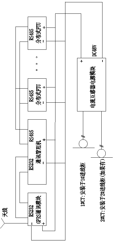
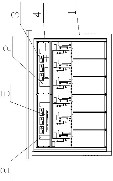
[0025] figure 1 It is the schematic diagram of the distribution network automation of the present invention. The present invention includes the secondary power supply part, the automation device part and the electric operation of the switch cabinet. It is composed of electric CT, current-to-voltage device and lithium iron phosphate battery; the automation device part is composed of GPRS module, communication management machine and small distributed FTU. A small distributed FTU is installed in each switch cabinet, and the 485 communication ports of all small distributed FTUs are connected to the communication management machine. The communication management machine realizes the signal interactive connection with the distribution network automation master station through the GPRS module. All small distributed FTUs, communication...


PUM


Abstract

The invention relates to the technical field of outdoor electrical devices, in particular to a ring main unit distribution automation reconstruction device. The ring main unit distribution automation reconstruction device comprises a secondary electric power supply device, an automation device and a switch cabinet electric operation mechanism, wherein a small CT passive electricity obtaining device serves as the secondary electric power supply device, the small CT passive electricity obtaining device is composed of an open-type electricity obtaining CT, a current-to-voltage device and a lithium iron phosphate storage battery, and the automation device is composed of a GPRS module, a communication manager and a small distributed FTU device. Due to the fact that the small CT passive electricity obtaining device is used instead of a PT to provide a secondary electric power supply, the small CT passive electricity obtaining device is small in occupied space, reconstruction can be directly carried out in an original outdoor box, and the time for reconstruction is greatly shortened; due to the fact that the small distributed FTU device is used, the defect that a centralized DTU screen is overlarge in size and cannot be installed in internal space of the original outdoor box is overcome; the ring main unit distribution automation reconstruction device can be universally applied to all the ring main units in the market. The ring main unit distribution automation reconstruction device has high practicability and universality, and is not limited by space.

Description

technical field [0001] The invention relates to the technical field of outdoor electrical equipment, in particular to a power distribution automation transformation device for a ring network cabinet and a transformation method thereof. Background technique [0002] As the last link in the transmission and distribution of electric energy, power distribution plays a very important role in power production. Due to historical reasons, the degree of automation of power distribution equipment in the past was not high. With the development of the economy and the improvement of living standards, higher requirements are put forward for the quality and reliability of power supply. After the large-scale transformation of the two networks, the layout of the distribution network has been optimized, and the reliability of the distribution network needs to be further improved. In order to achieve a high level of distribution network automation in an all-round way, it is even more urgent to...

Claims


Application Information

Patent Timeline
Patent Type & Authority Applications(China)
IPC IPC(8): H02B3/00
Inventor 章佳音孙卫成李雪松
Owner NATUS CHANGZHOU ELECTRIC
Why Eureka
Eureka Blog
Learn More