Thermally-induced fusing steel ball lock pressing and releasing mechanism
What is Al technical title?
Al technical title is built by PatSnap Al team. It summarizes the technical point description of the patent document.
A release mechanism and steel ball lock technology, applied in motor vehicles, aerospace equipment, aerospace equipment, etc., can solve the problems of poor temperature adaptability, large impact, high cost, etc., and achieve low unlocking impact, reliable locking and unlocking High reliability and low cost effect
Active Publication Date: 2021-07-16
SHANGHAI AEROSPACE SYST ENG INST
View PDF6 Cites 2 Cited by
Summary
Abstract
Description
Claims
Application Information
AI Technical Summary
This helps you quickly interpret patents by identifying the three key elements:
Problems solved by technology
Method used
Benefits of technology
Problems solved by technology
[0003] The object of the present invention is to overcome the defects and deficiencies of the prior art, and provide a heat-induced fusing steel ball lock compression release mechanism, which has simple structure, light weight, small unlocking impact, low cost, and wide temperature adaptability, which solves the problem of existing problems. The problems of heavy weight and high impact of pyrotechnics, poor temperature adaptability and high cost of memory alloy compression release mechanism
Method used
Image
Click on the blue label to locate the original text in one second.
Reading with bidirectional positioning of images and text.
Examples
Embodiment Construction
[0023] The invention will be described in more detail hereinafter with reference to the accompanying drawings showing embodiments of the invention. However, this invention may be embodied in many different forms and should not be construed as limited to the embodiments set forth herein. Rather, these embodiments are provided so that this disclosure will be thorough and complete, and will fully convey the scope of the invention to those skilled in the art.
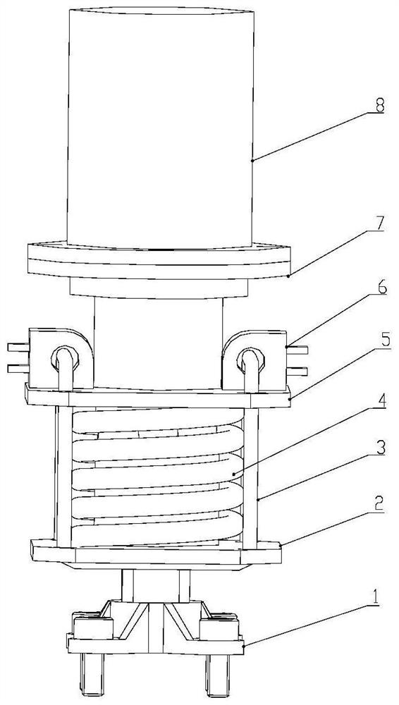
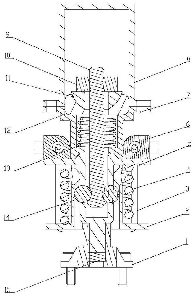
[0024] The embodiment of the present invention provides a heat-induced fuse steel ball lock compression release mechanism, including a base 1, a clamp 2, a restraint rope 3, an unlocking spring 4, a lock cylinder 5, a heater 6, a compression sleeve 7, a compression Take 8, hold down bar 9, pull pin spring 13, steel ball 14 and set screw 15; Wherein, described lock post 5 is made up of two sections of cylindrical structures with different cross-sectional sizes, and the upper section is a hollow large cylindrical section, Th...
PUM
Abstract
The invention discloses a thermally-induced fusing steel ball lock pressing and releasing mechanism which comprises a base, a hoop, a restraining rope, an unlocking spring, a lock column, a heater, a pressing sleeve, a pressing cap, a pressing rod, a locking nut, a force bearing bowl, a sliding block, a pin pulling spring, a steel ball and a set screw. Locking and releasing of the pressing and releasing mechanism are achieved through the relative position relation among the locking column, the clamping hoop and the pressing rod, an unlocking spring is installed between the locking column and the clamping hoop, and a restraining rope is bound between the locking column and the clamping hoop. The restraint rope restrains the position between the lock column and the hoop, so that the pressing and releasing mechanism is in a locked state, and the spring is in a compressed state; a heater is installed on the restraint rope, the heater is powered on, the restraint rope is fused, the unlocking spring pushes the hoop to move by a certain distance, and the pressing and releasing mechanism is changed into an unlocking and releasing state from a locking state. The pressing and releasing mechanism has the characteristics of simple structure, light weight, low impact, low cost, wide temperature adaptability, high locking and unlocking reliability and the like.
Description
technical field [0001] The invention relates to a compression release mechanism, in particular to a non-firework compression release mechanism. Background technique [0002] In recent years, micro-satellites have developed rapidly. Various structural products on them, such as small expandable solar wings, antennas, etc., need to be compressed in the folded state to withstand the load of the launch section. After entering orbit, they need to be separated and released so that the products can Expand to a predetermined position or shape. Traditional spacecraft often use pyrotechnic separation devices, which have the characteristics of large carrying capacity and reliable separation, but at the same time have disadvantages such as heavy weight, high cost, and large unlocking impact, which cannot well meet the needs of microsatellites. Therefore, it is necessary to develop a lightweight, low-cost, high-performance compression release mechanism. Contents of the invention [00...
Claims
Application Information
Patent Timeline
Application Date:The date an application was filed.
Publication Date:The date a patent or application was officially published.
First Publication Date:The earliest publication date of a patent with the same application number.
Issue Date:Publication date of the patent grant document.
PCT Entry Date:The Entry date of PCT National Phase.
Estimated Expiry Date:The statutory expiry date of a patent right according to the Patent Law, and it is the longest term of protection that the patent right can achieve without the termination of the patent right due to other reasons(Term extension factor has been taken into account ).
Invalid Date:Actual expiry date is based on effective date or publication date of legal transaction data of invalid patent.