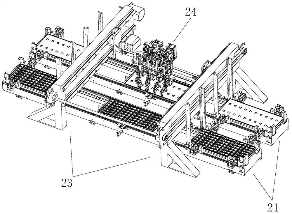
Chip tray changing equipment

A chip and equipment technology, applied in the field of chip changing equipment, can solve problems such as inability to adapt to adaptive positioning adjustment, market confusion, and inability to adjust, saving feeding time and reclaiming time, good moving stability, and improving efficiency. Effect

Active Publication Date: 2021-07-16
SHENZHEN GRAND INNOSYS CORP
View PDF32 Cites 8 Cited by
  • Summary
  • Abstract
  • Description
  • Claims
  • Application Information

AI Technical Summary

Problems solved by technology

[0002]In the production process of semiconductor integrated circuit chips, due to many links and complicated processes, some chips have been damaged during the production process. Launching chips into the market at the same time will inevitably cause confusion in the market, so before the chips enter the market, it is necessary to test the chips
The traditional chip inspection process is a labor-intensive process. The inspectors pick up the chip with tweezers, put it on the testing machine, and then press it manually to obtain the chip data. At present, the traditional chip inspection process is being phased out in the market. The most advanced inspection method is The efficiency of chip detection is greatly improved by simulating the manual detection action of the detection equipment. The chip is picked up by the mechanical gripper, which is fast and accurate. Pick and place, and chips are generally loaded with some general-purpose trays in the production process, and the existing devices for chip transfer between some general-purpose trays and special trays have limited efficiency during operation. It cannot be adjusted according to the distance of the loading unit of the tray, nor can it adapt to the outer dimensions of different trays for adaptive positioning adjustment, which is inconvenient

Method used


Image

  • Chip tray changing equipment
  • Chip tray changing equipment
  • Chip tray changing equipment

Examples


Embodiment Construction

[0047] The specific implementation manners of the present invention will be further described in detail below in conjunction with the accompanying drawings and embodiments. The following examples are used to illustrate the present invention, but are not intended to limit the scope of the present invention.

[0048] In the description of the present invention, it should be understood that unless otherwise specified and limited, the terms "installation", "connection" and "connection" used in the present invention should be interpreted in a broad sense, for example, it can be a fixed connection, or It can be a detachable connection or an integral connection; it can be a mechanical connection or an electrical connection; it can be a direct connection or an indirect connection through an intermediary, and it can be the internal communication of two components. Those of ordinary skill in the art can understand the specific meanings of the above terms in the present invention in spec...


PUM


Abstract

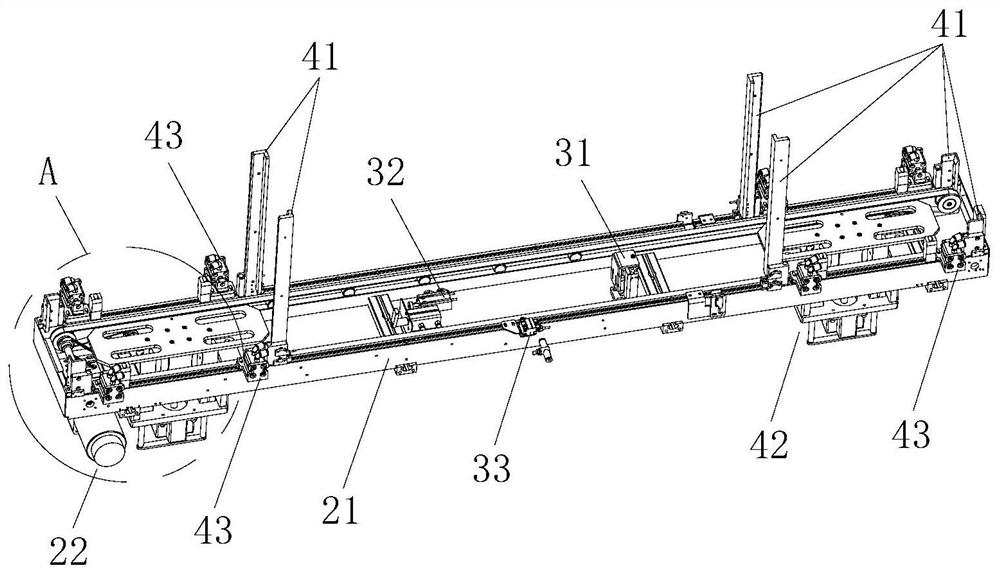
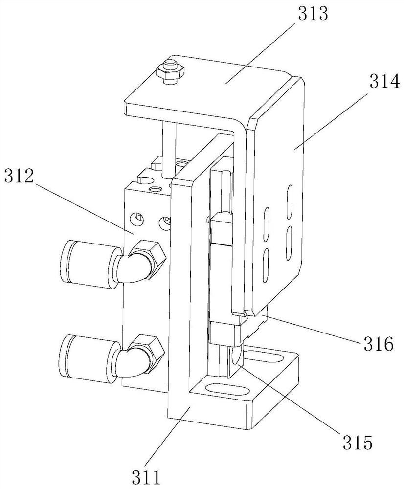
The invention discloses chip tray changing equipment which comprises at least two tray changing material tray conveying rails and a tray changing module. Each tray changing material tray conveying rail comprises a tray changing track main frame, a material tray conveying device and a material tray positioning device, wherein the material tray conveying device and the material tray positioning device are installed on the tray changing track main frame, the material tray conveying device is used for conveying universal material trays or special material trays to move on the tray changing track main frame, and the material tray positioning device is used for positioning the universal material trays or the special material trays; and the tray changing module comprises a tray changing moving frame and a tray changing gripper, the tray changing moving frame is used for driving the tray changing gripper to move, and the tray changing gripper can grab single chips or grab at least two chips in an opening and closing interval adjusting manner. The chip tray changing equipment can change the chips on the universal material trays into the special material trays, and also can change the chips on the special material trays into the universal material trays; the material trays can be adaptively positioned in stations; the disc changing gripper can be opened and closed to adjust the distance; and the chip tray changing efficiency is effectively improved.

Description

technical field [0001] The invention relates to the technical field of semiconductor integrated circuit chip swapping, in particular to a chip swapping device. Background technique [0002] In the production process of semiconductor integrated circuit chips, due to the many links and intricate processes, some chips have been damaged during the production process. If the damaged chips and normal chips are released to the market at the same time, it will definitely cause confusion in the market. Therefore, Before the chip enters the market, the chip needs to be tested. The traditional chip inspection process is a labor-intensive process. The inspectors pick up the chip with tweezers, put it on the testing machine, and then press it manually to obtain the chip data. At present, the traditional chip inspection process is being phased out in the market. The most advanced inspection method is The efficiency of chip detection is greatly improved by simulating the manual detection ...

Claims


Application Information

Patent Timeline
Patent Type & Authority Applications(China)
IPC IPC(8): B65G47/91B65G59/04B65G57/04B65G57/03B65G59/02
CPCB65G47/912B65G59/04B65G57/04B65G57/035B65G59/026
Inventor 林宜龙刘飞吴海裕唐召来廖生彪
Owner SHENZHEN GRAND INNOSYS CORP
Why Eureka
Try Eureka