
Continuous parallel traction method and traction device

A traction device and traction plate technology, applied in textiles, textiles, papermaking, looms, etc., can solve the problems of inconsistent tension control of adjacent fabrics, cumbersome process, improve production efficiency and fabric quality performance, and simplify the process. , the effect of rapid and continuous traction

Inactive Publication Date: 2021-07-16
NANJING FIBERGLASS RES & DESIGN INST CO LTD +1
View PDF11 Cites 1 Cited by
  • Summary
  • Abstract
  • Description
  • Claims
  • Application Information

AI Technical Summary

Problems solved by technology

[0004] The purpose of the present invention is to provide a continuous parallel traction method and traction device, which solves the problem of re-tying the yarn and performing tension control after the weaving of the next fabric in the existing three-dimensional weaving process. The process is cumbersome, and the tension control of adjacent pieces of fabric is inconsistent, etc.

Method used


Image

  • Continuous parallel traction method and traction device
  • Continuous parallel traction method and traction device
  • Continuous parallel traction method and traction device

Examples


Embodiment 1

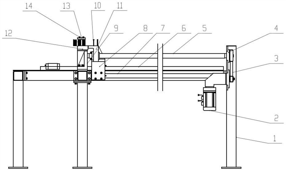
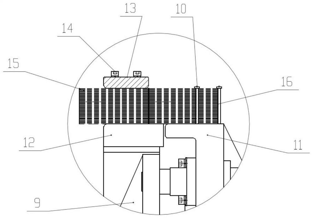
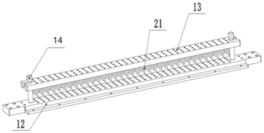
[0056] Such as Figure 1-3 As shown, a continuous parallel traction device, the device includes the following parts:

[0057] Drive mechanism: including servo motor 2 with reducer, transmission mechanism 3, screw rod 5 with flange, screw seat I4, screw seat II9; servo motor 2, screw seat I4, screw seat II7 through the inner hexagon The screws and nuts are installed on the frame 1; the two ends of the screw rod 5 are installed on the screw seat I4 and the screw seat II7; the transmission mechanism 3 is installed on the output shaft of the servo motor 2; the transmission mechanism 3 Installed on one end of the screw rod 5;

[0058] Guide mechanism: including linear slide rail I6 with slider, linear slide rail II7 with slider, and slider connecting corner piece 8; the linear slide rail I6 with slider and linear slide rail II7 with slider respectively use their The mounting surfaces of the sliders are installed on the frame 1 in a manner perpendicular to each other; the connecting...

Embodiment 2

[0073] Such as Figure 4 As shown, a continuous parallel traction device, the device includes the following parts

[0074] Traction guide mechanism: including sprocket 18 and chain plate 17;

[0075] Drive mechanism: used to drive the sprocket 18 to rotate;

[0076] Yarn tie mechanism: including detachable screws arranged on the chain plate 17;

[0077] Traction fixing mechanism: including the traction upper splint with acupuncture 21 and fixing bolts, the chain plate 17 is provided with holes corresponding to the acupuncture.

[0078] It also includes the control system and the installation mechanism of the traction upper splint;

[0079] The control system detects the length of the woven fabric, and according to the length of the woven fabric, controls the traction upper splint installation mechanism to install the traction upper splint, and clamps the reserved section of fabric.

[0080] A method for continuous traction using the above-mentioned traction device, compris...


PUM


Abstract

The invention belongs to the field of three-dimensional mechanisms, and particularly relates to a continuous parallel traction method and traction device. The traction device comprises a yarn tying mechanism used for tying yarns when a first fabric is woven, a traction fixing mechanism for clamping woven yarns at a weaving section reserved behind the first fabric in the weaving process and pre-pressing unwoven yarns to the horizontal plane, a traction guide mechanism for enabling the yarn tying mechanism and the traction fixing mechanism to move thereon and performing traction in three-dimensional fabric weaving, and a driving mechanism which provides power for the traction guide mechanism. According to the traction device, the traction fixing mechanism and the traction guide and driving mechanisms capable of driving the traction fixing mechanism to reciprocate are arranged, so that the traction is stable and reliable, the operation is easy, continuous weaving of a fabric can be achieved, the consistency of yarn tension is guaranteed, and the preparation efficiency and the consistency of product quality are improved.

Description

technical field [0001] The invention belongs to the field of three-dimensional mechanisms, and in particular relates to a continuous parallel traction method and a traction device. Background technique [0002] At present, the three-dimensional woven fabrics used in aerospace have the characteristics of large thickness and large dimensions. The traditional roller take-up and traction method will cause indentation and wrinkles on the fabric, which will cause irreparable damage to the fabric. At the same time, the friction between the upper and lower surfaces will cause surface friction. The burrs destroy the fabric characteristics, so the traditional traction method is not suitable for the traction of thicker three-dimensional woven fabrics. [0003] The fabric traction device of the flat knitting machine with the application number 200710004060.0, the knitted fabric traction device of the flat knitting machine with the application number 200620003142.4, and the new fabric tr...

Claims


Application Information

Patent Timeline
Patent Type & Authority Applications(China)
IPC IPC(8): D03D41/00D03D49/04
CPCD03D41/004D03D49/04
Inventor 阮见潘梁李沛虹胡方田瞿书涯徐钦冉梁素兰
Owner NANJING FIBERGLASS RES & DESIGN INST CO LTD
Learn More