Block-assembled capillary heat exchanger and assembling method thereof

A capillary tube and heat exchanger technology, applied in the field of block-type assembled capillary tube heat exchanger and its assembly, can solve the problems of small tube diameter, cumbersome, complicated operation, etc., so as to improve welding efficiency, reduce maintenance work, and improve wear and tear. The effect of tube efficiency

Pending Publication Date: 2021-07-16
INST OF ENGINEERING THERMOPHYSICS - CHINESE ACAD OF SCI
View PDF0 Cites 2 Cited by
  • Summary
  • Abstract
  • Description
  • Claims
  • Application Information

AI Technical Summary

Problems solved by technology

The small diameter, large number and dense arrangement make the tube threading process of the capillary heat exchanger extremely cumbersome, and most of the manpower and time consumption during the processing of the capillary heat exchanger are concentrated in the tube threading step
[0004] The processing of the existing capillary heat exchanger is similar to that of the traditional shell-and-tube heat exchanger. The tube sheet is an integrated structure. The capillary tubes are inserted into the tube sheet and baffle one by one by manual pipe penetration, which is cumbersome to operate and low in efficiency; At the same time, the welding of the tube sheet and the capillary is also completed by vacuum brazing in a vacuum brazing furnace at one time, and there are certain welding problems in vacuum brazing. The probability is greater, which will lead to leakage problems in the entire capillary heat exchanger, and the later maintenance work will become more cumbersome due to the large number of capillary tubes
The cumbersomeness of the traditional process greatly limits the processing, production and wide application of capillary heat exchangers, and also causes the cost of capillary heat exchangers to be at a relatively high level

Method used


Image

  • Block-assembled capillary heat exchanger and assembling method thereof
  • Block-assembled capillary heat exchanger and assembling method thereof
  • Block-assembled capillary heat exchanger and assembling method thereof

Examples


Embodiment Construction

[0027] In order to make the object, technical solution and advantages of the present invention clearer, the present invention will be further described in detail below in conjunction with specific embodiments and with reference to the accompanying drawings.

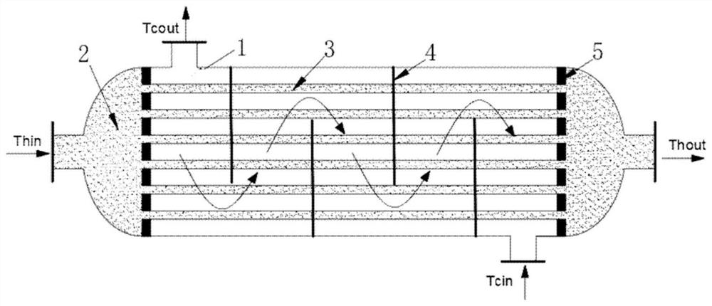
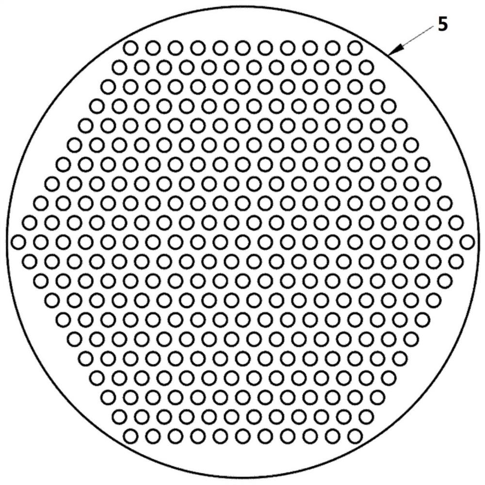
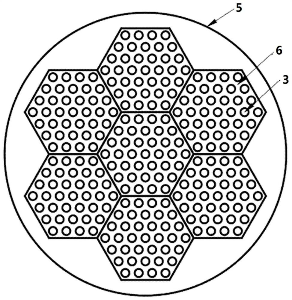
[0028] The present invention provides a capillary tube heat exchanger assembled in blocks. The capillary tube heat exchanger includes: a shell 1 , a tube box space 2 , a heat transfer tube 3 , a baffle plate 4 , and a tube plate 5 .

[0029] figure 1 Schematic diagram of the capillary heat exchanger.

[0030] like figure 1 As shown, the capillary heat exchanger includes: a shell 1, a tube box space 2 is formed inside, a first fluid inlet Thin and a first fluid output Thout are arranged at both ends of the shell 1, and on the shell 1 The other two ends are provided with a second fluid inlet Tcin and a second fluid outlet Tcout; a plurality of heat transfer tubes 3 are arranged in the tube box space 2 and communicate with...


PUM


Abstract

The invention discloses a block-assembled capillary heat exchanger which comprises a shell, a plurality of heat transfer tubes, a plurality of baffle plates and a tube plate, wherein a tube box space is formed in the shell, a first fluid inlet and a first fluid outlet are arranged at two ends of the shell, and a second fluid inlet and a second fluid outlet are arranged at the other two ends of the shell; the heat transfer tubes are arranged in the pipe box space and communicate with the first fluid inlet and the first fluid outlet; the baffle plates are provided with through holes matched with the arrangement mode of the heat transfer tubes, and all the baffle plates are arranged on the heat transfer tubes in a penetrating mode through the through holes; and the tube plate comprises a plurality of tube plate sub-units which can be assembled together, N tube holes are formed in each tube plate sub-unit, each tube hole is independently welded to one heat transfer tube, and N is an integer greater than or equal to 1.

Description

technical field [0001] The invention relates to the technical field of fluid heat exchange, in particular to a block-assembled capillary heat exchanger and an assembly method thereof. Background technique [0002] With the rise of supercritical carbon dioxide power generation and the wide application of supercritical carbon dioxide heat pumps, traditional heat exchangers are difficult to meet the requirements of high-efficiency and compact systems, and it is necessary to develop new high-temperature, high-pressure compact heat exchangers. The structure of the capillary heat exchanger is similar to that of the traditional shell-and-tube heat exchanger. Compared with the traditional shell-and-tube heat exchanger, it has stronger tolerance, better heat transfer performance, and higher compactness, which can effectively reduce the cost of the new power generation system. At the same time, compared with other types of high-temperature and high-pressure heat exchangers such as pri...

Claims


Application Information

Patent Timeline
Patent Type & Authority Applications(China)
IPC IPC(8): F28D7/16F28F9/013F28F9/26
CPCF28D7/16F28F9/0131F28F9/26F28F2275/06
Inventor 王涛蔡浩飞姜玉雁谭思聪郭朝红郭聪梁世强
Owner INST OF ENGINEERING THERMOPHYSICS - CHINESE ACAD OF SCI
Why Eureka
Try Eureka