Unlock instant, AI-driven research and patent intelligence for your innovation.

Low-position sector cutting blasting method for pre-splitting forming groove cavity

A technology of forming grooves and sectors, which is applied in the field of low-position sector-shaped cutting blasting, to achieve the effects of low cost, reduced scale and ballast consumption, and reduced workload of ballast accumulation and removal.

Active Publication Date: 2021-07-16
SHANDONG UNIV OF SCI & TECH +5
View PDF0 Cites 0 Cited by
  • Summary
  • Abstract
  • Description
  • Claims
  • Application Information

AI Technical Summary

Problems solved by technology

The present invention focuses on solving the problem of over-excavation areas formed at the bottom of the cut hole and the over-excavation area at the mouth of the cavity, so that the scattering distance and range of flying rocks blasted in the opposite direction can be controlled

Method used


Image

  • Low-position sector cutting blasting method for pre-splitting forming groove cavity
  • Low-position sector cutting blasting method for pre-splitting forming groove cavity
  • Low-position sector cutting blasting method for pre-splitting forming groove cavity

Examples


Embodiment 1

[0034] A low-position fan-shaped cutting blasting method for a pre-splitting shaped cavity, the steps comprising:

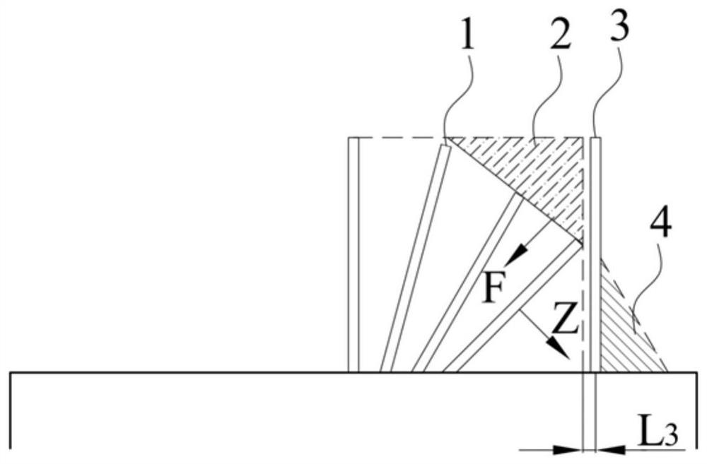
[0035] S1. Drill multiple rows of cut holes 1 arranged in a fan shape on the excavation face, and the plane determined by each row of cut holes 1 is parallel to the bottom plate; the angle between each row of cut holes 1 and the excavation face is arranged from small to large .

[0036] Cutting holes 1 are all arranged on one side of the vertical center line of the excavation face, avoiding the other side where the equipment on the excavation face is concentrated. Arranged in order of increasing length. The bottom row of cut holes arranged in a fan shape is adjacent to the bottom plate holes. The distance between the uppermost row of cut holes arranged in a fan shape and the bottom plate is less than 120cm. By reducing the height of the cutting part, the initial throwing height of the blasting flying rock is reduced, thereby effectively controlling the throwin...

Embodiment 2

[0047] A low-level fan-shaped cutting blasting method for pre-split forming grooves is implemented in the blasting and excavation construction process of the North Second Auxiliary Transportation Roadway in a coal mine. The basic situation of the excavation face is as follows: the excavation height of the excavation face of the North Second Auxiliary Transport Roadway is 375cm, the excavation width is 540cm, and the excavation area is 17.1m 2 , the lithology is siltstone. The three-grade water-gel explosive allowed in coal mines is adopted, with a working capacity of 220ml, a detonation velocity of 3000m / s, a sharpness of 10mm, a roll diameter of 35mm, a length of 40cm, and a mass of 400g / roll. Use the integrated drilling machine 8 to drill holes, the length of the drill pipe is 200cm, and the maximum blasthole length of drilling is 185cm. Use the permissible electric detonator for coal mines in the 1st to 5th section. Before blasting, the drilling, loading and transporting ...


PUM


Abstract

The invention provides a low-position sector cutting blasting method for a pre-splitting forming groove cavity, and relates to the technical field of tunnel engineering blasting. The problem that blasting flying stones damage tunneling working face equipment is solved. The method comprises the steps that a plurality of rows of cutting holes arranged in a sector shape are drilled in a tunneling working face, and the plane determined by each row of cutting holes is parallel to a bottom plate; pre-splitting holes are drilled in the sides, adjacent to first blasting holes, of the sector cutting holes; the cutting holes and the pre-splitting holes are filled with explosives and detonators; a ballast pile is placed between the tunneling working face and protection equipment, and the ballast pile and the sector cutting holes are oppositely arranged; and the pre-splitting holes are detonated before the cutting holes, and the cutting holes are detonated according to the sequence that acute angles formed by each row of cutting holes and the tunneling working face are increased. According to the method, the clamping effect of rocks is reduced through the pre-splitting forming groove cavity, the stability of the minimum resistance line of the adjacent auxiliary blasting holes is guaranteed, and the throwing direction and the throwing range of the cutting blasting flying stones are controlled by reducing the height of the cutting part, arranging the ballast pile and the like.

Description

technical field [0001] The invention relates to the technical field of tunnel engineering blasting, in particular to a low-position fan-shaped cutting blasting method for a pre-splitting shaped cavity. Background technique [0002] In the process of tunnel excavation, in order to improve the blasting efficiency, it is often necessary to increase the amount of charge at the cutting part to achieve a good blasting effect. The throwing distance of flying rocks produced by conventional cutting and blasting methods is usually 20m to 30m from the working face, and some flying rocks can reach 40m to 50m. Blasting flying rocks will cause serious damage to equipment and facilities near the excavation face. In coal mine rock roadway excavation construction, in order to improve the mechanization level of roadway drilling and blasting construction, the integrated drilling, loading and transporting machine has been used in roadway excavation construction. Due to the structural characte...

Claims


Application Information

Patent Timeline
IPC IPC(8): F42D1/00F42D1/08F42D3/04
CPCF42D1/00F42D1/08F42D3/04
Inventor 王海亮姜世斌周华荣于福郭守坤李川孟祥慧张海义于建新周勇赵军赵琛
Owner SHANDONG UNIV OF SCI & TECH