High-temperature reactor waste heat removal system

A waste heat removal system and high-temperature reactor technology, applied in reactors, greenhouse gas reduction, climate sustainability, etc., can solve problems such as slow cooling rate, long time-consuming, incomplete flushing, etc.

Pending Publication Date: 2021-07-16
XIAN THERMAL POWER RES INST CO LTD
View PDF0 Cites 1 Cited by
  • Summary
  • Abstract
  • Description
  • Claims
  • Application Information

AI Technical Summary

Problems solved by technology

[0003] The purpose of the present invention is to provide a high-temperature reactor waste heat discharge system, which adopts the method of combining forced circulation and natural circulation, and fundamentally solves the shortcomings of the existing waste heat discharge system such as slow cooling rate, long time consumption, and incomplete flushing.

Method used


Image

  • High-temperature reactor waste heat removal system

Examples


Embodiment Construction

[0022] Exemplary embodiments of the present disclosure will be described in more detail below with reference to the accompanying drawings. Although exemplary embodiments of the present disclosure are shown in the drawings, it should be understood that the present disclosure may be embodied in various forms and should not be limited by the embodiments set forth herein. Rather, these embodiments are provided for more thorough understanding of the present disclosure and to fully convey the scope of the present disclosure to those skilled in the art. It should be noted that, in the case of no conflict, the embodiments of the present invention and the features in the embodiments can be combined with each other. The present invention will be described in detail below with reference to the accompanying drawings and examples.

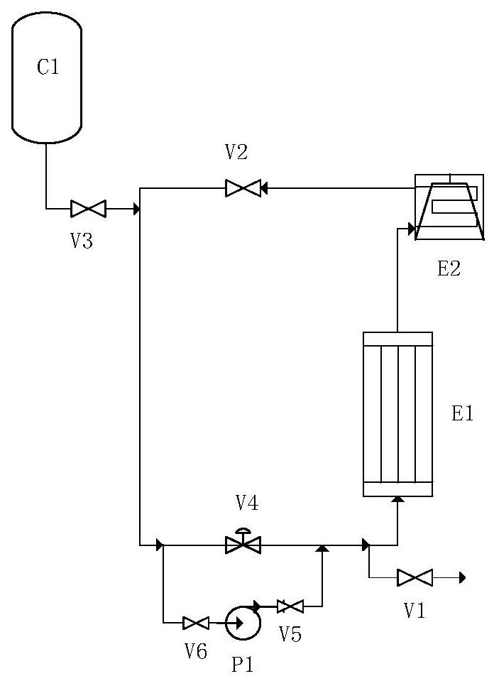
[0023] The currently designed waste heat removal system is a closed system composed of water-cooled wall heat exchanger E1 inside the cabin, air cooler E2 out...


PUM


Abstract

The invention discloses a high-temperature reactor waste heat removal system. The system comprises a water-cooled wall heat exchanger (E1) in a cabin, and an air cooler (E2) and an expansion water tank (C1) which are arranged outside the cabin, wherein an outlet of the water-cooled wall heat exchanger (E1) is connected to an inlet of the air cooler (E2), and an outlet of the air cooler (E2) and an outlet of the expansion water tank (C1) are connected to an inlet of the water-cooled wall heat exchanger (E1) through a forced circulation control valve (V4); and bypasses are arranged at the inlet end and the outlet end of the forced circulation control valve (V4), and forced circulation pumps (P1) are arranged on the bypasses. A method of combining forced circulation and natural circulation is adopted in the invention, so the defects that an existing waste heat removal system is low in cooling rate, long in consumed time, not thorough in flushing and the like are fundamentally overcome.

Description

technical field [0001] The invention belongs to the field of nuclear power high-temperature gas-cooled reactors, and in particular relates to a high-temperature reactor waste heat discharge system. Background technique [0002] High-temperature gas-cooled reactor is a new type of reactor with the characteristics of fourth-generation nuclear power, and its main feature is its inherent safety. The function of the waste heat removal system is to take out the heat of the reactor cabin through natural circulation during the normal operation period of the reactor or after the reactor is shut down, so as to quickly cool down the cabin and control the temperature of the cabin below 200°C. The waste heat removal system currently designed is a closed system composed of the water wall inside the cabin, the air cooler outside the cabin and the expansion tank. The air cooler exchanges heat with the atmosphere to cool down, and finally circulates naturally to the bottom of the water wall...

Claims


Application Information

Patent Timeline
Patent Type & Authority Applications(China)
IPC IPC(8): G21C15/18G21C15/243
CPCG21C15/18G21C15/243Y02E30/30
Inventor 张瑞祥
Owner XIAN THERMAL POWER RES INST CO LTD
Why Eureka
Try Eureka