Wide voltage input four-tube buck-boost circuit

A wide voltage input and circuit technology, which is applied in the direction of converting DC power input to DC power output, electrical components, and adjusting electrical variables, can solve the problems of reverse polarity of output voltage and harsh selection of switch tube withstand voltage, etc., and achieve reduction Low cost, stable and simple drive circuit, and high reliability

Active Publication Date: 2022-04-15
MORNSUN GUANGZHOU SCI & TECH
View PDF0 Cites 0 Cited by
  • Summary
  • Abstract
  • Description
  • Claims
  • Application Information

AI Technical Summary

Problems solved by technology

[0004] In view of this, the present invention can be mainly used to solve the problem of harsh selection of switching tube withstand voltage in high-voltage products, and at the same time can solve the problem of reverse polarity of the output voltage of traditional Buck-Boost, has automatic voltage equalization function, and the driving circuit is simple and reliable ,Easy to implement

Method used


Image

  • Wide voltage input four-tube buck-boost circuit
  • Wide voltage input four-tube buck-boost circuit
  • Wide voltage input four-tube buck-boost circuit

Examples


no. 1 example

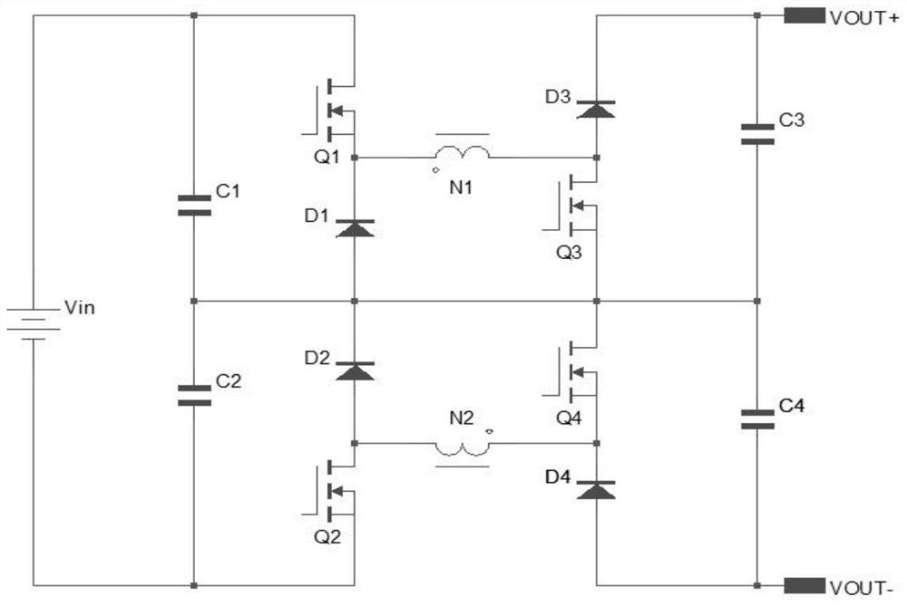
[0023] image 3 It is the schematic diagram of the wide voltage input Buck-Boost circuit of the first embodiment, which includes capacitor C1, capacitor C2, capacitor C3, capacitor C4, switch Q1, switch Q2, switch Q3, switch Q4, diode D1, diode D2 , diode D3, diode D4, coupled inductance and neutral line, wherein the coupled inductance is composed of winding inductance N1 and winding inductance N2;

[0024] Its connection relationship is as follows:

[0025] The anode of the input power supply Vin is connected to the drain of the switch tube Q1, and the source of the switch tube Q1 is connected to the cathode of the diode D1 and the end of the winding inductance N1 of the coupled inductor; the first end of the capacitor C1 is connected to the positive terminal of the input power supply Vin, and the capacitor C1 The second end of the capacitor C2 is connected to the first end of the capacitor C2; the first end of the capacitor C2 is connected to the cathode of the diode D2 and...

no. 2 example

[0029] Such as Figure 4 As shown, it is the schematic diagram of the wide voltage input Buck-Boost circuit of the second embodiment of the present invention. Compared with the first embodiment, the difference lies in that the resistor R1, the resistor R2, the resistor R3, the resistor R4 and the capacitor C5 are added.

[0030] Its connection relationship is as follows:

[0031] The anode of the input power supply Vin is connected to the first end of the capacitor C1, the first end of the resistor R1 and the drain of the switch Q1; the second end of the capacitor C1 is connected to the first end of the capacitor C2; the source of the switch Q1 is connected to the diode D1 The cathode of the winding inductance N1 and the end of the same name; the first end of the capacitor C2, the second end of the resistor R1, the first end of the resistor R2, the cathode of the diode D2 and the anode of the diode D1, the second end of the capacitor C2 is connected to the input power supply ...

no. 3 example

[0034] Such as Figure 5 As shown, it is the schematic diagram of the wide-voltage input Buck-Boost circuit of the third embodiment of the present invention. Compared with the second embodiment, the difference is that the freewheeling diode D1, diode D2, diode D3, and diode D4 are replaced with switches Tube Q5, switch tube Q6, switch tube Q7, switch tube Q8.

[0035] Its connection relationship is as follows:

[0036] The positive pole of the input power supply Vin is connected to the first end of the capacitor C1, the first end of the resistor R1 and the drain of the switch tube Q1; the second end of the capacitor C1 is connected to the first end of the capacitor C2; the source of the switch tube Q1 is connected to the switch tube The drain of Q5 and the end of the same name of the winding inductance N1; the first end of the capacitor C2 is connected to the second end of the resistor R1, the first end of the resistor R2, the source of the switch Q5 and the drain of the swit...


PUM


Abstract

The patent of the present invention discloses a wide voltage input Buck-Boost circuit, including capacitor C1, capacitor C2, capacitor C3, capacitor C4, capacitor C5, switch tube Q1, switch tube Q2, switch tube Q3, switch tube Q4, diode D1, Diode D2, diode D3, diode D4, resistor R1, resistor R2, resistor R3, resistor R4, winding inductance N1 and winding inductance N2. It can be applied to the field of DC-DC converters with wide voltage input range and high requirements on the withstand voltage of MOS tubes. The four switch tubes are connected in series with voltage division, which can solve the requirements for the switch tube withstand voltage selection when doing high voltage. At the same time, the circuit can also solve the problem of uneven voltage division due to inconsistent parameters of the switch tubes; when the working mode of the four switch tubes is the same on and off, only one synchronous drive signal is needed. Yes, the design difficulty of the driving circuit is reduced, and the circuit topology can avoid the reverse polarity problem of the traditional topology.

Description

technical field [0001] The invention relates to the field of switching power supply design, and is especially suitable for wide-voltage input Buck-Boost circuits. Background technique [0002] In the industrial and civil fields, it is often necessary to rectify the alternating current of various power grids into direct current. In order to make the switching power supply meet the global grid standard, the input voltage of the switching power supply needs to be designed to meet the requirements of a wide range of input voltage. [0003] In general, the higher the withstand voltage of the switch tube, the corresponding increase in the on-resistance Rds will cause the temperature rise of the switch tube, the efficiency will decrease, and the price of the single unit will be higher. For example, when a product needs 1500VDC input, the withstand voltage of a single switch tube (usually up to 1200V) can no longer meet the requirements. At this time, multiple MOS tubes can only be ...

Claims


Application Information

Patent Timeline
Patent Type & Authority Patents(China)
IPC IPC(8): H02M3/158H02M1/32
CPCH02M3/1582H02M1/32
Inventor 不公告发明人
Owner MORNSUN GUANGZHOU SCI & TECH
Why Eureka
Try Eureka