Flue gas purification system used in continuous smelting process

A technology of flue gas purification system and smelting process, which is applied in the field of flue gas purification system, and can solve problems such as environmental thermal pollution, high flue gas temperature, and reduced flue gas purification effect

Inactive Publication Date: 2021-07-20
武汉奇佳宇绿色环保科技有限公司
View PDF8 Cites 0 Cited by
  • Summary
  • Abstract
  • Description
  • Claims
  • Application Information

AI Technical Summary

Problems solved by technology

[0004] 1. When the existing flue gas purification equipment purifies the flue gas produced by metal smelting, there is no cooling process for the newly generated flue gas, and the metal smelting is carried out in a high temperature environment, and the temperature of the flue gas generated is also Very high, if the flue gas is not cooled, even after the flue gas is purified, it will still cause thermal pollution to the environment due to its high temperature;
[0005] 2. When the existing flue gas purification equipment purifies the flue gas produced by metal smelting, the time for the flue gas to pass through the purification equipment is too short to be completely purified, and the purification equipment is used to purify harmful gases and harmful particles in the flue gas It is difficult to replace the chemicals in time, so that the purification effect of the flue gas will be seriously reduced after the chemicals are exhausted, and the unpurified flue gas will be discharged into the air, causing environmental pollution

Method used


Image

  • Flue gas purification system used in continuous smelting process
  • Flue gas purification system used in continuous smelting process
  • Flue gas purification system used in continuous smelting process

Examples


Embodiment Construction

[0031] In order to make the technical means realized by the present invention, creative features, goals and effects easy to understand, the following combination Figure 1 to Figure 6 , to further elaborate the present invention.

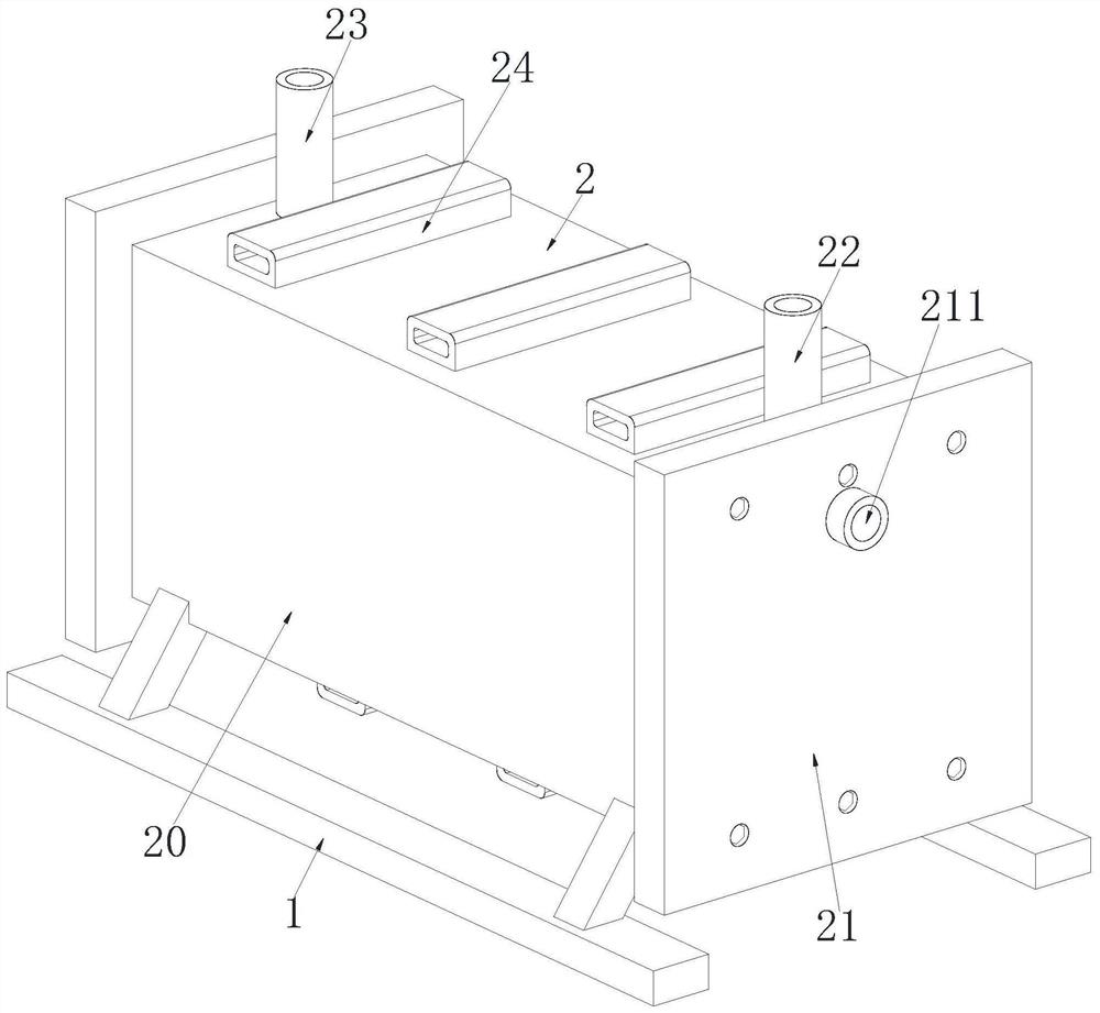
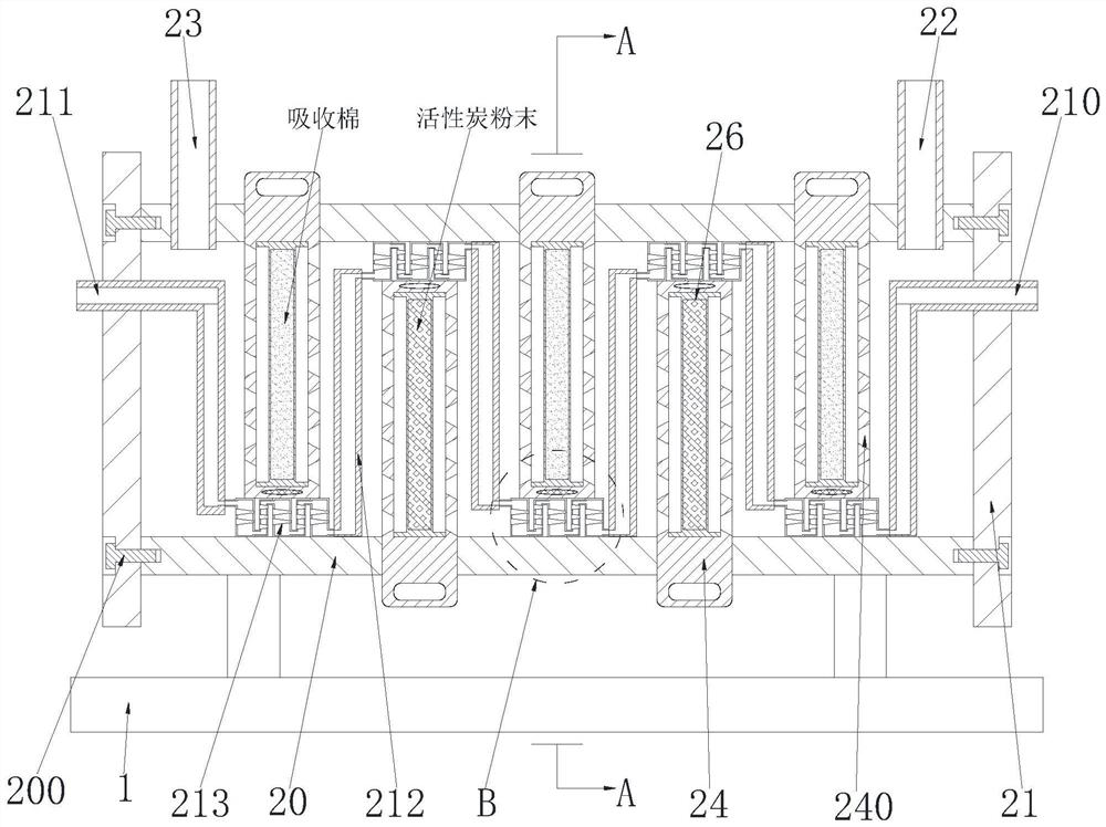
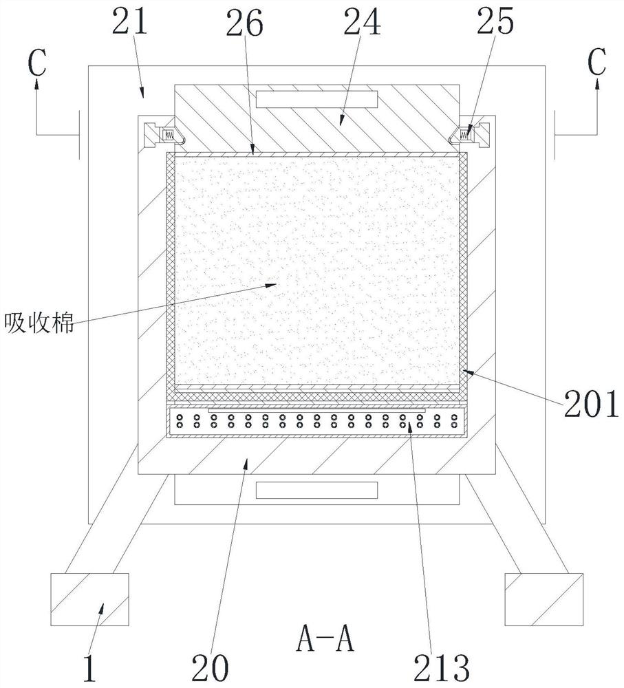
[0032] A flue gas purification system used in a continuous smelting process, comprising a support base 1 and a purification unit 2, two support bases 1 are arranged symmetrically, and a purification unit 2 is provided between the upper ends of the two support bases 1; wherein:

[0033] The purification unit 2 includes a purification pipeline 20, a purification sealing plate 21, an air inlet pipe 22, an air outlet pipe 23, a mounting frame 24, a limit branch chain 25 and an absorption plate 26, and a purification pipeline is arranged between the upper ends of the two support bases 1 20. The cross-section of the purification pipeline 20 is a square structure, the two ends of the purification pipeline 20 are symmetrically installed with purification se...


PUM


Abstract

The invention relates to a flue gas purification system used in a continuous smelting process. The flue gas purification system comprises two supporting seats and a purification unit, the two supporting seats are symmetrically arranged, and the purification unit is arranged between the upper ends of the two supporting seats. The invention can solve the current problems that the just generated flue gas is not cooled, the metal smelting is carried out in a high-temperature environment, the temperature of the generated flue gas is very high, the flue gas is not cooled, and even if the flue gas is purified, the flue gas still causes thermal pollution to the environment due to the too high temperature of the flue gas; and the time for flue gas to pass through purification equipment is too short, the flue gas is difficult to thoroughly purify, chemicals for purifying harmful gas and harmful particles in the flue gas in the purification equipment are difficult to replace in time, so that the purification effect on the flue gas is severely reduced after the chemicals are used up, and the flue gas which is not purified is discharged into the air, and environmental pollution is caused.

Description

technical field [0001] The invention relates to the field of environmental protection, in particular to a flue gas purification system used in a continuous smelting process. Background technique [0002] Due to the rapid development of society, the impact on the environment is also increasing. Therefore, environmental protection is the guarantee for human survival. One of the environmental pollution is the substances that pollute the environment during the metal smelting process. Smelting is a refining technology that uses methods such as roasting, smelting, electrolysis, and the use of chemicals to extract metals from ores and reduce the amount of metals contained in them. During the metal smelting process, many harmful gases will be produced, such as: carbon monoxide, sulfur dioxide, hydrogen sulfide, etc., and some harmful particles, such as: silicon If the gas and particles are directly discharged into the atmosphere without purification, it will cause serious pollution...

Claims


Application Information

Patent Timeline
IPC IPC(8): F27D17/00F23J15/02F23J15/06
CPCF27D17/004F27D17/008F23J15/025F23J15/06
Inventor 胡天宇
Owner 武汉奇佳宇绿色环保科技有限公司
Why Eureka
Try Eureka