
Hub flange plate combined machining center

A combined processing and hub flange technology, used in metal processing equipment, metal processing mechanical parts, manufacturing tools, etc., can solve the problem of inability to ensure the smoothness of the hub flange, poor machining accuracy of the hub flange, and inability to process workpieces, etc. problems, to achieve the effect of achieving simplicity, ensuring work continuity, and improving the finish of tapping

Pending Publication Date: 2021-07-23
邢台郭工机械制造有限公司
View PDF0 Cites 0 Cited by
  • Summary
  • Abstract
  • Description
  • Claims
  • Application Information

AI Technical Summary

Problems solved by technology

In this method, the workpiece needs to be frequently rotated and replaced to complete the three processing procedures of drilling, chamfering, and tapping. When the tool is replaced, the workpiece cannot be processed, the equipment works discontinuously, and the work efficiency is relatively low.
[0005] Moreover, the tool magazine works with the mechanical arm of the same equipment, and only the same coolant can be used in the drilling and tapping processes, which is poor in pertinence, and the coolant can only be suitable for a certain process in drilling and tapping , resulting in poor machining accuracy of the hub flange, the smoothness of the hub flange after processing cannot be guaranteed, and the product quality is relatively low

Method used


Image

  • Hub flange plate combined machining center
  • Hub flange plate combined machining center
  • Hub flange plate combined machining center

Examples


Embodiment

[0030] Embodiment A combined machining center for hub flanges

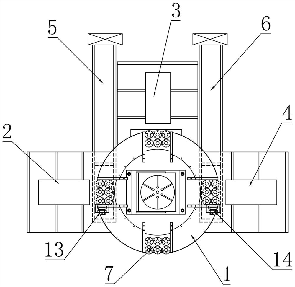
[0031] like figure 1 As shown, this embodiment includes a rotary table 1 , and a drilling mechanism 2 , a chamfering mechanism 3 and a tapping mechanism 4 that are circularly distributed around the rotary table 1 along the rotation direction of the rotary table 1 . When machining the hub flange, the rotary table 1 can quickly transfer the workpiece, thereby ensuring that the drilling mechanism 2, chamfering mechanism 3 and tapping mechanism 4 can respectively complete the corresponding drilling, chamfering and tapping operations on the workpiece.

[0032] In this embodiment, a first chip removal machine 5 and a second chip removal machine 6 are respectively provided under the rotary table 1 and on both sides of the chamfering mechanism 3 . The first chip removal machine 5 is located below the working position of the drilling mechanism 2, and includes the first scraper conveyor and the first filtered water tank lo...


PUM


Abstract

The invention belongs to the technical field of hub flange plate machining, and discloses a hub flange plate combined machining center. The machining center comprises a rotary workbench, a drilling mechanism, a chamfering mechanism, a tapping mechanism and a plurality of tool clamps detachably installed on the rotary workbench, and the drilling mechanism, the chamfering mechanism and the tapping mechanism are annularly distributed around the rotary workbench. A first chip removal machine and a second chip removal machine are arranged at the two sides of the chamfering mechanism correspondingly. The first chip removal machine is arranged below a working position of the drilling mechanism, and the second chip removal machine is arranged below a working position of the tapping mechanism; and each tool clamp comprises a base detachably mounted on the rotary workbench and a plurality of clamp assemblies fixedly arranged on the base through mounting plates. When a hub flange plate is machined, three machining procedures of drilling, chamfering and tapping can be completed on the same rotary workbench through the different machining mechanisms, the working efficiency is improved, meanwhile, the smoothness of the machined hub flange plate can be improved, and the product quality is guaranteed.

Description

technical field [0001] The invention belongs to the technical field of wheel hub flange processing, and in particular relates to a combined machining center for wheel hub flanges. Background technique [0002] During the production of the hub flanges of motorcycles and automobiles, three processing procedures of drilling, chamfering and tapping are required. At present, there are generally two ways to realize the above-mentioned processing procedures for the hub flanges, but both of them have The deficiencies, specifically: [0003] 1. Use different equipment on different machine tools to complete the three processing procedures of drilling, chamfering and tapping. In this method, the workpiece needs to be turned around and positioned and clamped multiple times on different machine tools to complete the three processing procedures of drilling, chamfering, and tapping. Multiple positioning and clamping seriously consume a lot of time for workers. Very inefficient. [0004]...

Claims


Application Information

Patent Timeline
Patent Type & Authority Applications(China)
IPC IPC(8): B23P23/02B23Q11/00
CPCB23P23/02B23Q11/0042
Inventor 郭金锋
Owner 邢台郭工机械制造有限公司
Learn More