A non-clogging high-suction self-priming pump

A self-priming pump, high suction lift technology, applied in the direction of pumps, pump components, pump devices, etc., to prevent precision drop, improve service life, and increase the effect of heat dissipation

Active Publication Date: 2022-08-09
ESKE PUMP
View PDF7 Cites 0 Cited by
  • Summary
  • Abstract
  • Description
  • Claims
  • Application Information

AI Technical Summary

Problems solved by technology

[0003] The purpose of the present invention is to provide a non-clogging high-suction self-priming pump to solve the following technical problems: (1) The heat dissipation effect of the bearing seat can be effectively increased through the design of two heat dissipation layers in the inner cavity of the bearing seat. It can facilitate the adjustment of the spindle and prevent the occurrence of deviation and precision drop caused by overheating of the spindle during rotation. Through the setting of the buffer spring, the vibration generated during the rotation of the spindle can be buffered to a certain extent, effectively improving the use of the spindle. (2) The self-priming pump drives the screw auger and the serpentine stirring rod to rotate at the same time when the water is delivered through the setting of the rotating shaft and the telescopic shaft. The auger can cooperate with the negative pressure in the pump body cavity to increase the water delivery efficiency At the same time, it can improve the efficiency of water passing through the filter plate. The structure of the serpentine stirring rod prevents some impurities from passing through the filter plate and entering the water inlet pipe to precipitate and affect the water delivery; (3) Through the lifting design of the spiral auger, the The impurities between the filter plate and the sealing valve core are transported to the processing chamber, and the cleaning roller in the processing chamber can be cleaned by the auger during rotation, which is convenient for the auxiliary transportation of water by the subsequent auger

Method used


Image

  • A non-clogging high-suction self-priming pump
  • A non-clogging high-suction self-priming pump
  • A non-clogging high-suction self-priming pump

Examples


Embodiment Construction

[0029]The technical solutions in the embodiments of the present invention will be clearly and completely described below with reference to the accompanying drawings in the embodiments of the present invention. Obviously, the described embodiments are only a part of the embodiments of the present invention, but not all of the embodiments. Based on the embodiments of the present invention, all other embodiments obtained by those of ordinary skill in the art without creative efforts shall fall within the protection scope of the present invention.

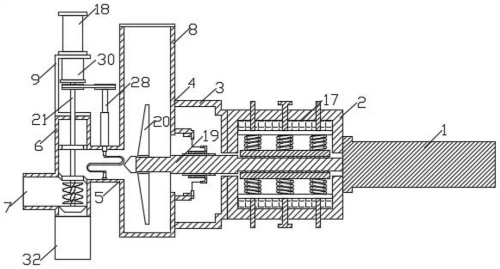
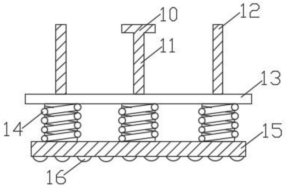
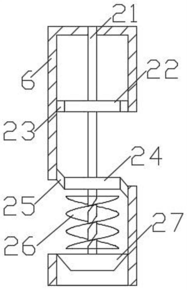
[0030] see Figure 1-6 As shown in the figure, the present invention is a self-priming pump with no blockage and high suction stroke, including a fixed motor 1, a bearing seat 2, an end cover 3, a pump body 4, a water inlet pipe 5, and an impeller 20. The bearing seat 2 is rotatably installed with two The lead screw 11 is fixedly connected with the lift plate 13, a plurality of buffer springs 14 are installed on the lift plate 13, an a...


PUM


Abstract

The invention discloses a self-priming pump with no clogging and high suction, which comprises a fixed motor, a bearing seat, an end cover, a pump body, a water inlet pipe and an impeller. Two lead screws are rotatably mounted on the bearing seat, and the lead screws are fixedly connected with a lifting plate. , A number of buffer springs are installed on the lifting plate, an adjustment plate is installed at one end of the buffer springs away from the lifting plate, a number of balls are installed on the adjustment plate, a main shaft is installed at the end of the output shaft of the fixed motor, and the main shaft is between the two adjustment plates. The inner cavity of the seat is provided with two heat dissipation layers. The present invention can effectively increase the heat dissipation effect of the bearing seat through the design of the two heat dissipation layers in the inner cavity of the bearing seat, the self-priming pump can facilitate the adjustment of the main shaft, and prevent the occurrence of deviation and precision degradation caused by overheating during the rotation of the main shaft. In some cases, through the setting of the buffer spring, the vibration generated during the rotation of the main shaft can be buffered to a certain extent, and the service life of the main shaft can be effectively improved.

Description

technical field [0001] The invention relates to the technical field of self-priming pump design, in particular to a non-clogging high-suction self-priming pump. Background technique [0002] Self-priming pump is a self-priming centrifugal pump, which has the advantages of compact structure, convenient operation, stable operation, easy maintenance, high efficiency, long life, and strong self-priming ability. There is no need to install a bottom valve in the pipeline, and it is only necessary to ensure that there is a quantitative liquid in the pump body before work. During the use of the existing self-priming pump, the main shaft is prone to deflection due to overheating of rotation, and at the same time, the main shaft is prone to vibration of a certain magnitude during long-term use. At the same time, the existing self-priming pump usually has a certain filter structure at the water inlet position, which easily reduces the efficiency of water delivery, and at the same time...

Claims


Application Information

Patent Timeline
Patent Type & Authority Patents(China)
IPC IPC(8): F04D7/04F04D13/06F04D29/62F04D29/044F04D29/046F04D29/58F04D29/00F04D29/70F04D29/66
CPCF04D7/045F04D13/06F04D29/628F04D29/044F04D29/046F04D29/5893F04D29/007F04D29/708F04D29/669Y02W10/10
Inventor 曲昌平孙才军曹珠明
Owner ESKE PUMP
Why Eureka
Try Eureka