Three-way connector capable of automatically cutting off liquid leakage
A tee joint, automatic technology, applied in the field of tee joints and tee joints, can solve the problems of loose bolts, shunt pipes and tee joints falling off, and loose joints between shunt pipes and tee joints.
- Summary
- Abstract
- Description
- Claims
- Application Information
AI Technical Summary
Problems solved by technology
Method used
Image

Examples
Embodiment 1
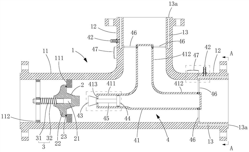
[0041] Such as Figure 1-Figure 4 As shown, this embodiment provides a three-way joint that can automatically shut off the flow of liquid leakage, which includes a joint body 1 , a valve core 2 , an elastic component 3 and a pneumatic component 4 .
[0042] The joint body 1 includes a main connecting pipe 11 and two branch connecting pipes 12, wherein the main connecting pipe 11 is used to connect with the main pipeline, and the two branch connecting pipes 12 are respectively used to connect with corresponding branch pipes, and the main connecting pipe 11 and the branch connecting pipes The connecting pipes 12 are distributed in a T-shape; moreover, gas grooves 13 are formed inside the pipe walls of the two branching pipes 12 for accommodating gas filled therein, and the openings 13a of the gas grooves 13 are located on the end faces of the branching pipes 12 .
[0043] The valve core 2 is arranged in the inner cavity of the main connecting pipe 11 , and the valve core 2 can m...
Embodiment 2
[0068] Such as Figure 6 As shown, the difference between this embodiment and Embodiment 1 is that the structure of the gas tank 13 and the cylinder 41 is different, but the functions are the same, specifically:
[0069] The gas groove 13 includes a first gas groove 131, a second gas groove 132 and a connection groove 133, wherein the first gas groove 131 is arranged inside the pipe wall of one of the branch pipes 12, and the second gas groove 132 is arranged in the other Inside the pipe wall of a branch pipe 12, the connection groove 133 is arranged between the first gas groove 131 and the second gas groove 132 to communicate with the two, and the first gas groove 131 and the second gas groove 132 are all connected to each other in the branch pipe. The opening 13a is formed on the end surface of the connecting pipe 12, and the opening 13a is in the form of a ring on the end surface of the connecting pipe 12; the cylinder 41 is arranged in the inner cavity of the joint body 1 ...
Embodiment 3
[0071] Such as Figure 7 As shown, the difference between this embodiment and Embodiment 1 is that the structure of the gas tank 13 and the cylinder 41 is different, but the functions are the same, specifically:
[0072]The gas groove 13 includes a first gas groove 131, a second gas groove 132 and a connection groove 133, wherein the first gas groove 131 is arranged inside the pipe wall of one of the branch pipes 12, and the second gas groove 132 is arranged in the other Inside the pipe wall of a branch pipe 12, the connection groove 133 is arranged between the first gas groove 131 and the second gas groove 132 to communicate with the two, and the first gas groove 131 and the second gas groove 132 are all connected to each other in the branch pipe. The opening 13a is formed on the end surface of the connecting pipe 12, and the opening 13a is in the form of a ring on the end surface of the connecting pipe 12; the cylinder 41 is arranged in the inner cavity of the joint body 1 i...
PUM
 Abstract
Description
Claims
Application Information
 - R&D
- Intellectual Property
- Life Sciences
- Materials
- Tech Scout
- Unparalleled Data Quality
- Higher Quality Content
- 60% Fewer Hallucinations
Browse by: Latest US Patents, China's latest patents, Technical Efficacy Thesaurus, Application Domain, Technology Topic, Popular Technical Reports.
© 2025 PatSnap. All rights reserved.Legal|Privacy policy|Modern Slavery Act Transparency Statement|Sitemap|About US| Contact US: help@patsnap.com