Guide spray pipe of rotary detonation combustion chamber

A combustion chamber and nozzle technology, applied in the combustion chamber, continuous combustion chamber, combustion method, etc., to achieve the effect of improving the overall propulsion performance, stabilizing the flight attitude, and eliminating torque

Active Publication Date: 2021-07-23
NORTHWESTERN POLYTECHNICAL UNIV
View PDF14 Cites 2 Cited by
  • Summary
  • Abstract
  • Description
  • Claims
  • Application Information

AI Technical Summary

Problems solved by technology

The invention can be used in fields such as detonation propulsion

Method used


Image

  • Guide spray pipe of rotary detonation combustion chamber
  • Guide spray pipe of rotary detonation combustion chamber
  • Guide spray pipe of rotary detonation combustion chamber

Examples


Embodiment 1

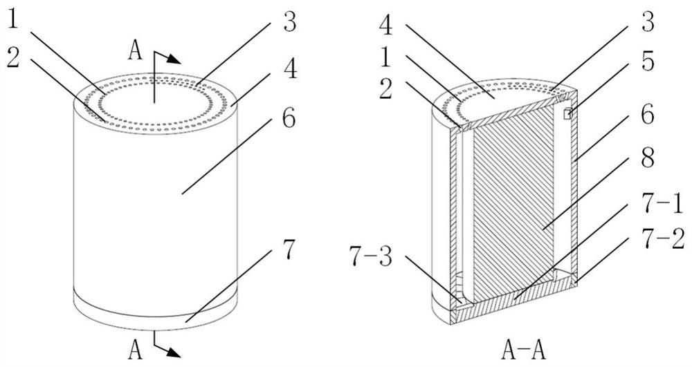
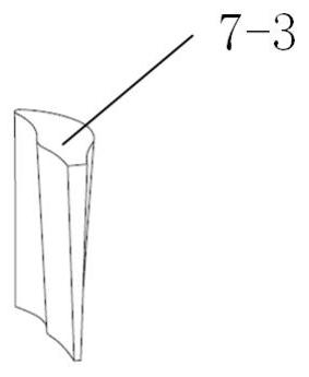
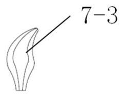
[0053] see figure 1 , In this example, an annular combustion chamber is adopted, the outer ring 7-2 of the guide nozzle is directly connected with the outer ring 6 of the combustion chamber, and the center body of the guide nozzle 7-1 is connected with the inner column 8 of the combustion chamber. Because the width of the combustion chamber is relatively small, the angles of the outside and the inner outlet airflow of the guide nozzle 7 inlet are similar, so straight guide nozzle blades 7-3 can be used (see figure 2 and image 3 ), which deflects the circumferential speed of the airflow to the axial speed, and continues to expand and accelerate until it is discharged along the axial direction, so as to improve the overall propulsion performance, and at the same time, it can eliminate the torque originally generated by the outlet swirl and stabilize the flight attitude of the aircraft.

Embodiment 2

[0055] see Figure 4 , In this example, an empty barrel combustion chamber is used, and the outer ring 7-2 of the guide nozzle is directly connected with the outer ring 6 of the combustion chamber. Because the combustion chamber has no inner column, the overall vane height of the guide vane 7-3 is relatively large, and the center body 7-1 of the guide nozzle and the outer ring 7-2 of the guide nozzle are used to fix the guide vane 7-3. The outside of the guide nozzle 7 inlet and the inboard outlet airflow angle differ greatly, and the twist guide nozzle blade 7-3 can be used (referring to Figure 4 and Figure 5 ), which deflects the circumferential speed of the airflow to the axial speed, and continues to expand and accelerate until it is discharged along the axial direction, so as to improve the overall propulsion performance, and at the same time, it can eliminate the torque originally generated by the outlet swirl and stabilize the flight attitude of the aircraft.


PUM


Abstract

The invention provides a guide spray pipe of a rotary detonation combustion chamber. The guide spray pipe comprises a rotary detonation combustion chamber body and a guide spray pipe body. Inert media are jetted at one side of an ignition system, and detonation waves can only be propagated in the reverse direction away from the inert media after ignition so as to control the rotational flow direction of outlet airflow. The guide spray pipe is arranged at a combustion chamber outlet, a guide blade of the guide spray pipe is fixed by a guide spray pipe outer ring and a center body, a front half section mean camber line of the blade is bent, the front edge direction is consistent with the airflow deflection angle of the combustion chamber outlet, and a rear half section mean camber line is a straight line, and the direction is consistent with the axial direction of the combustion chamber; and the circumferential velocity of the airflow at the combustion chamber outlet is deflected to be the axial velocity, and the expansion acceleration continues until the airflow is discharged in the axial direction. According to the guide spray pipe, the circumferential kinetic energy of the airflow in the rotary detonation combustion chamber can be effectively utilized, so that the torque generated by rotational flow in the original exhaust process can be eliminated, the flight attitude of an aircraft can be stabilized, and the overall propulsion performance can be improved. The guide spray pipe can be used in the fields of detonation propulsion and the like.

Description

technical field [0001] The invention relates to the field of detonation propulsion, in particular to a guide nozzle of a rotary detonation combustion chamber. Background technique [0002] Rotating Detonation Engine (RDE), as a new concept power device, has potential advantages such as simple structure, high thermal cycle efficiency, and small entropy increase. It has broad application prospects and has become a research hotspot at home and abroad in recent years. [0003] In existing research, rotating detonation combustors are generally divided into two structural types: annular (with inner column) and empty barrel (without inner column). Fuel and oxidant are injected from one end (the head of the combustion chamber), and the detonation wave propagates in the circumferential direction to consume the combustible gas mixture. The high-temperature and high-pressure gas expands backward to do work and is discharged from the other open end (the tail of the combustion chamber). ...

Claims


Application Information

Patent Timeline
Patent Type & Authority Applications(China)
IPC IPC(8): F23R3/38
CPCF23R3/38Y02T50/60
Inventor 王可朱亦圆赵明皓李清安于潇栋黄忻昱范玮
Owner NORTHWESTERN POLYTECHNICAL UNIV
Why Eureka
Try Eureka