Backflow combustion chamber casing head structure, manufacturing method thereof and engine combustion chamber

A backflow combustor and combustor technology, which is applied in the field of engine combustors and gas turbine engine combustors, can solve problems such as stress, large load, impact on engine safety, and easy local deformation, so as to avoid stress concentration and increase casing Weight, avoiding the effect of scratching

Active Publication Date: 2021-07-23
AECC HUNAN AVIATION POWERPLANT RES INST
View PDF8 Cites 1 Cited by
  • Summary
  • Abstract
  • Description
  • Claims
  • Application Information

AI Technical Summary

Problems solved by technology

[0004] The invention provides a casing head structure of a backflow combustion chamber and its manufacturing method and an engine combustion chamber to solve the problem that the stress and load on the casing head of the existing combustion chamber are large, exceed the stress limit allowed by the material, and be easy to use. Local deformation occurs, which affects the technical problems of engine safety

Method used


Image

  • Backflow combustion chamber casing head structure, manufacturing method thereof and engine combustion chamber
  • Backflow combustion chamber casing head structure, manufacturing method thereof and engine combustion chamber
  • Backflow combustion chamber casing head structure, manufacturing method thereof and engine combustion chamber

Examples


Embodiment Construction

[0032] It should be noted that, in the case of no conflict, the embodiments in the present application and the features in the embodiments can be combined with each other. The present invention will be described in detail below with reference to the accompanying drawings and examples.

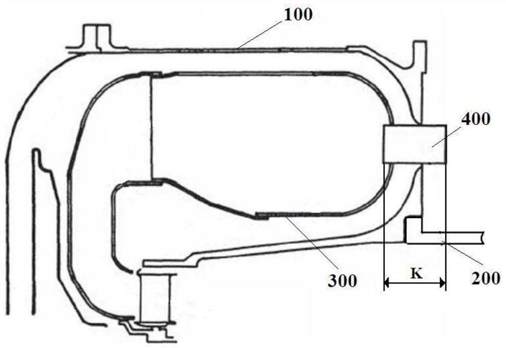
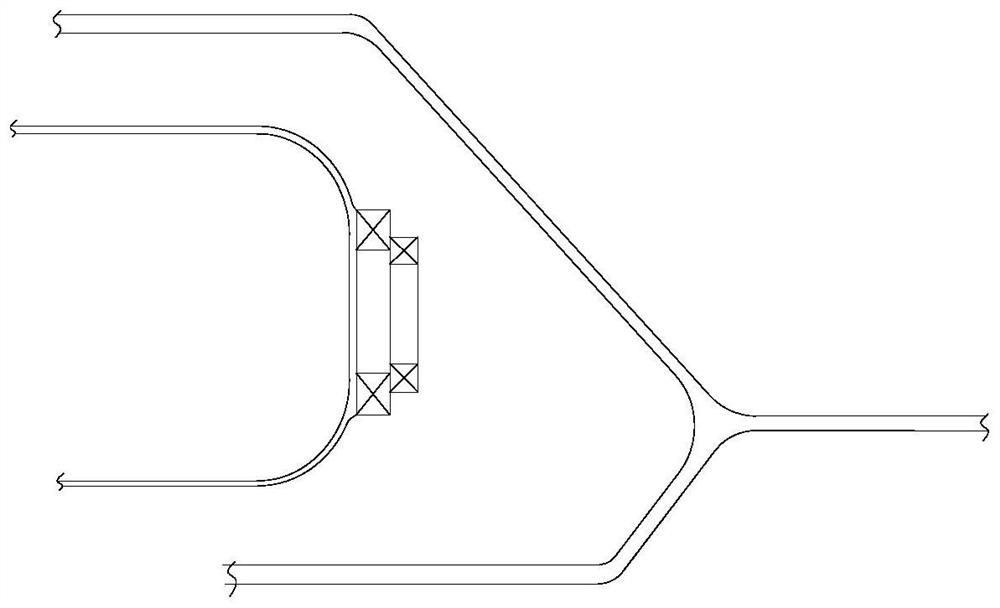
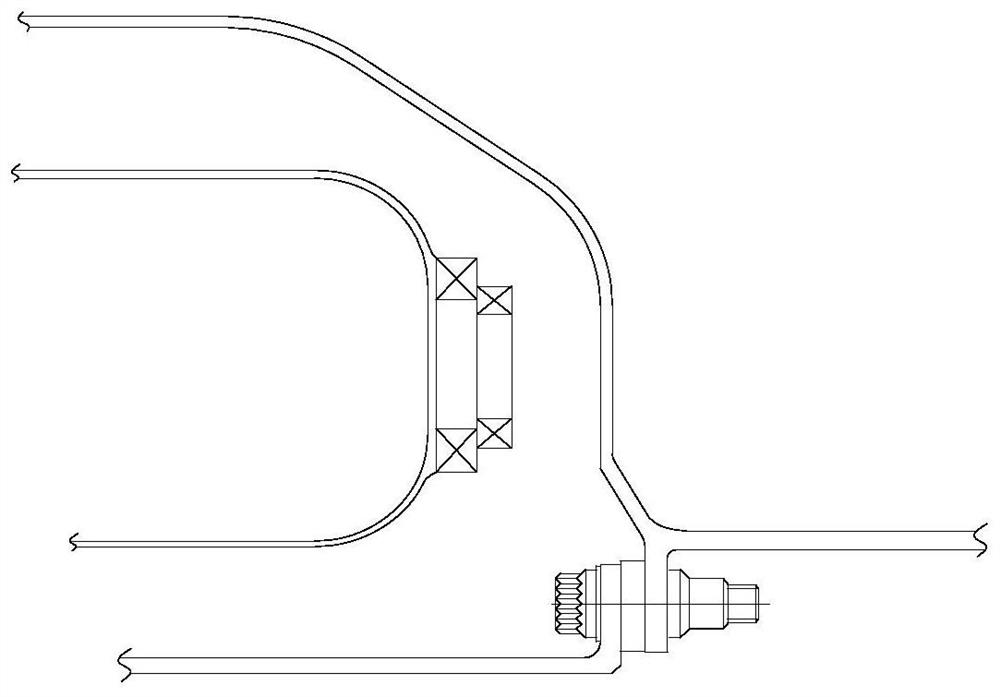
[0033] figure 1 is the schematic diagram of the backflow combustor; figure 2 It is a schematic diagram of the head structure of the inclined-plane combustion chamber casing; image 3 It is a schematic diagram of the head structure of the stepped combustion chamber casing; Figure 4 It is a structural diagram of the casing head of the backflow combustion chamber in the preferred embodiment of the present invention; Figure 5 It is the A-A sectional view of the preferred embodiment of the present invention; Figure 6 It is a B-B sectional view of a preferred embodiment of the present invention; Figure 7 It is a C-C sectional view of a preferred embodiment of the present invention.

[0034...


PUM


Abstract

The invention discloses a backflow combustion chamber casing head structure, a manufacturing method thereof and an engine combustion chamber. The backflow combustion chamber casing head structure adopts an annular base structure and comprises arch-shaped bearing beams and nozzle parts which are alternately arranged along the circumferential direction of the annular base structure, and the arch-shaped bearing beams and the nozzle parts are in smooth transition connection by adopting arc surfaces. The arch-shaped bearing beams are of a base body structure with the cross sections in an arch shape, and the radial size of the arch-shaped bearing beams is gradually reduced in the direction from a combustion chamber case to a turbine case. Each nozzle part comprises a nozzle mounting surface and a connecting surface, each nozzle mounting surface is positioned between every two adjacent arch-shaped bearing beams and is parallel to the head part of a flame tube, each connecting surface is positioned at the bottom end of each nozzle mounting surface and is vertical to each nozzle mounting surface, and the nozzle mounting surfaces are in smooth transition connection with the connecting surfaces. The backflow combustion chamber casing head structure forms a similar frame type structure, does not deform when being subjected to load action, always ensures concentricity of a rotor and a stator of an engine, and avoids the problems of scraping, abrasion, vibration and the like of the rotor.

Description

technical field [0001] The invention relates to the field of combustion chambers of gas turbine engines, and in particular, relates to a casing head structure of a return flow combustion chamber. In addition, the present invention also relates to a manufacturing method including the casing head structure of the above-mentioned backflow combustion chamber and an engine combustion chamber. Background technique [0002] In the field of small and medium-sized aero-engines, in the combustion chamber of a gas turbine engine, the combustion chamber casing is used as the casing of the combustion chamber components, and its main function is to contain and support the flame tube, form the internal flow path of the engine, and at the same time undertake the compressor casing and the turbine casing . As an important load-bearing part of the engine, the combustor casing not only bears the high-pressure pressure of the combustion chamber itself, but also needs to transmit the aerodynamic...

Claims


Application Information

Patent Timeline
Patent Type & Authority Applications(China)
IPC IPC(8): F23R3/54F23R3/60
CPCF23R3/54F23R3/58
Inventor 王启道蔡志斌石小祥王梅娟邬俊黄伟刘瑶
Owner AECC HUNAN AVIATION POWERPLANT RES INST
Why Eureka
Try Eureka