Fiber grating humidity sensor and manufacturing method thereof
A technology of humidity sensor and optical fiber grating, which is applied in the direction of instruments, thermometers, scientific instruments, etc., can solve problems such as waste, influence of humidity-sensitive characteristics, and degradation of surface coating performance, and achieve the effects of easy replacement and guaranteed coating quality
Pending Publication Date: 2021-07-23
AIR FORCE ENG UNIV OF PLA AIRCRAFT MAINTENACE MANAGEMENT SERGEANT SCHOOL
View PDF0 Cites 0 Cited by
- Summary
- Abstract
- Description
- Claims
- Application Information
AI Technical Summary
Problems solved by technology
[0002] Because the fiber grating sensor has the advantages of strong anti-electromagnetic interference, good flexibility, corrosion resistance, light weight, etc., it can overcome many shortcomings of the traditional humidity sensor, so it has been well developed. The existing fiber grating sensors are based on it The humidity-sensitive material is covered to monitor the relative humidity. However, after a long period of repeated use, the moisture-sensitive material layer will be deteriorated or worn due to factors such as environmental corrosion, and its humidity-sensitive characteristics will be affected. The existing practice is Directly replace the new sensor and throw away the old one. However, the replaced fiber optic SPR probe is good, only the deterioration or wear of the surface coating leads to a decline in performance, and direct throwing away causes a certain amount of waste.
Method used
View moreImage
Smart ImageViewing Examples
Examples
Embodiment
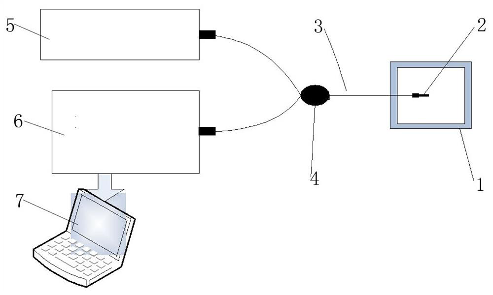
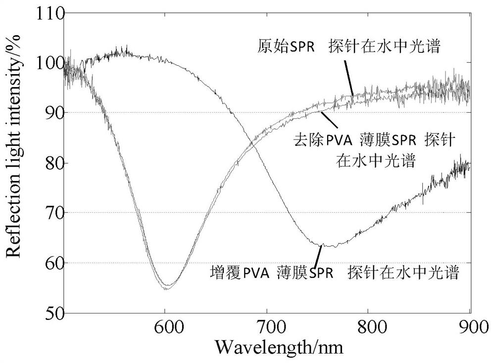
[0032] Example: see figure 1 , figure 2 , image 3 , Figure 4 , Figure 5 , Figure 6 , Figure 7 , Figure 8 , Figure 9 , Figure 10 and Figure 11 . In the figure, 1-adjustable humidity chamber, 2-optical fiber SPR probe, 3-multimode optical fiber, 4-Y-type optical fiber coupler, 5-broadband light source, 6-optical fiber spectrum demodulator, 7-PC.
Login to View More PUM
 Abstract
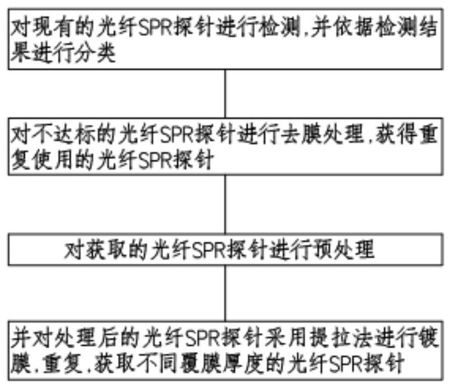
The invention discloses a fiber bragg grating humidity sensor. A manufacturing method of the sensor comprises the steps of detecting an existing optical fiber SPR probe and classifying according to a detection result; carrying out film removal treatment on a substandard optical fiber SPR probe to obtain a reusable optical fiber SPR probe; carrying out pretreatment on the obtained optical fiber SPR probe; and coating the treated optical fiber SPR probe with a coating film by adopting a pulling method, and repeating to obtain optical fiber SPR probes with different coating film thicknesses. According to the method, the optical fiber SPR probe with intact performance is obtained by carrying out reversible treatment on the optical fiber SPR probe with coating failure, the optical fiber SPR probe is coated again, effective optical fiber SPR probes with different coating thicknesses are obtained, and the method has the functions of waste utilization and resource saving.
Description
Technical field: [0001] The invention relates to a temperature sensor, in particular to a fiber grating humidity sensor. Background technique: [0002] Because the fiber grating sensor has the advantages of strong anti-electromagnetic interference, good flexibility, corrosion resistance, light weight, etc., it can overcome many shortcomings of the traditional humidity sensor, so it has been well developed. The existing fiber grating sensors are based on it The humidity-sensitive material is covered to monitor the relative humidity. However, after a long period of repeated use, the moisture-sensitive material layer will be deteriorated or worn due to factors such as environmental corrosion, and its humidity-sensitive characteristics will be affected. The existing practice is Directly replace the new sensor and throw away the old one. However, the replaced fiber optic SPR probe is good, only the deterioration or wear of the surface coating leads to a decline in performance, an...
Claims
Login to View More Application Information
Patent Timeline
 Patent Type & Authority Applications(China)
IPC IPC(8): G01K11/3206
CPCG01K11/3206
Inventor 高涛黄旌韩梅杨钰郭辉陈璞李猛郭娟
Owner AIR FORCE ENG UNIV OF PLA AIRCRAFT MAINTENACE MANAGEMENT SERGEANT SCHOOL
Features
- R&D
- Intellectual Property
- Life Sciences
- Materials
- Tech Scout
- Unparalleled Data Quality
- Higher Quality Content
- 60% Fewer Hallucinations
Learn More Browse by: Latest US Patents, China's latest patents, Technical Efficacy Thesaurus, Application Domain, Technology Topic, Popular Technical Reports.
© 2025 PatSnap. All rights reserved.Legal|Privacy policy|Modern Slavery Act Transparency Statement|Sitemap|About US| Contact US: help@patsnap.com


