
Oil supply system for valve clearance-equalizing hydraulic tappets

A technology of oil supply system and hydraulic tappet, which is applied in the direction of valve device, engine components, machine/engine, etc., and can solve the problem of oil passage emptying and so on

Pending Publication Date: 2021-07-23
PEZHO SITROEN AUTOMOBILS SA
View PDF6 Cites 0 Cited by
  • Summary
  • Abstract
  • Description
  • Claims
  • Application Information

AI Technical Summary

Problems solved by technology

At least one disadvantage of the device disclosed in DE 44 28 681 A1 can be considered that in the standstill state of the internal combustion engine, all oil channels are emptied

Method used


Image

  • Oil supply system for valve clearance-equalizing hydraulic tappets
  • Oil supply system for valve clearance-equalizing hydraulic tappets
  • Oil supply system for valve clearance-equalizing hydraulic tappets

Examples


Embodiment Construction

[0033] The description that follows is merely illustrative in nature. For purposes of clarity, the same reference numbers have been used in the drawings to refer to similar elements. The supply lines can be realized via boreholes in the component or via pipes connected thereto.

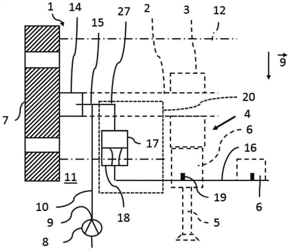
[0034] figure 1 An oil supply system 1 for supplying oil to a camshaft 2 is shown. Some components, such as the cam 3 , which actuates the valve 5 via the load path 4 , require oil as coolant and lubricant. The valve 5 can be an inlet valve or an outlet valve of an internal combustion engine not shown otherwise. A hydraulic tappet 6 is located in the load path 4 . The hydraulic tappet 6 is filled with oil in order to compensate possible play in the load path 4 .

[0035] Oil is delivered to outlet 9 by oil pump 8 . The outlet 9 is connected in a flow-conducting manner to a first supply line 10 . In the ready-to-operate installation position of the internal combustion engine, the first supply li...


PUM


Abstract

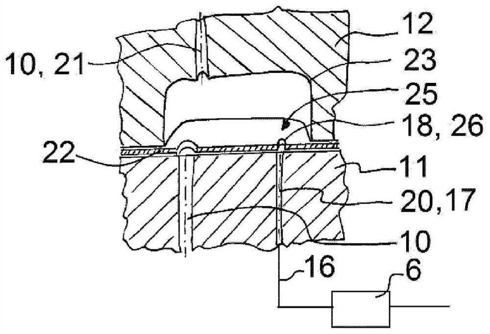
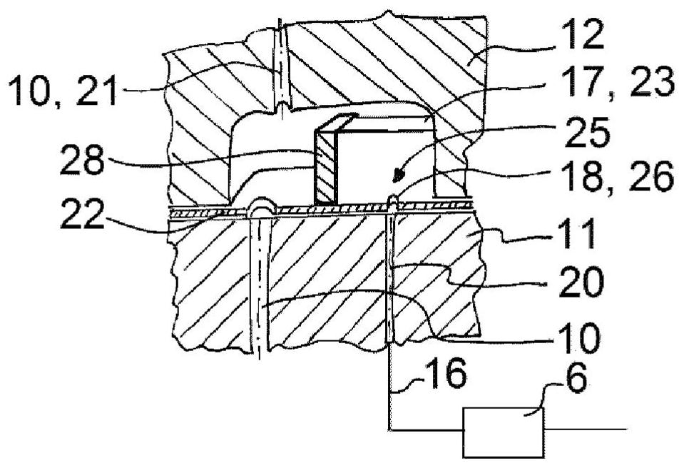
The invention relates to an oil supply system (1) for valve clearance-equalizing hydraulic tappets (5) of an internal combustion engine. The system comprises a first supply line (10), which connects an outlet (9) of an oil pump (8) in a fluid-conducting manner to an assembly of a camshaft drive; a second supply line (20), which leads, in a fluid-conducting manner, from a branch (15) of the first supply line (10) to an oil gallery (16) for the valve clearance-equalizing hydraulic tappets (6), wherein the branch (15) is arranged in an operationally ready installation position of the internal combustion engine above the oil gallery (16) of the valve clearance-equalizing hydraulic tappets (6).

Description

technical field [0001] The present disclosure relates to an oil supply system for a hydraulic tappet compensating valve play in an internal combustion engine. Background technique [0002] An oil supply system is to be understood as meaning a system which is designed to provide pressurized and unpressurized oil in an internal combustion engine for the following non-exhaustive list of functions: [0003] - manipulation of movable components, such as camshaft adjustments, [0004] - supply of oil for lubrication and cooling to the camshaft drive for operating the inlet and outlet valves, and [0005] - Supply of auxiliary units with oil for lubrication and cooling. [0006] For this purpose, the oil supply system can have an oil pump and a plurality of lines connected in a flow-conducting manner to the pressure side of the oil pump. The lines can be formed by pipes and by bores in the motor block or the cylinder head and the camshaft module. The camshaft is rotatably mount...

Claims


Application Information

Patent Timeline
Patent Type & Authority Applications(China)
IPC IPC(8): F01L1/053F01L1/24
CPCF01L1/053F01L1/24F01L2001/34423F01L2001/2444F01L2810/02
Inventor J·拉策尔J·齐默尔曼R·瓦尔泰
Owner PEZHO SITROEN AUTOMOBILS SA
Learn More