Side-channel compressor for a fuel cell system for conveying and/or compressing a gaseous medium

A fuel cell system, gaseous medium technology, applied to components of pumping devices for elastic fluids, liquid fuel engines, machines/engines, etc., can solve the problem of side channel compressors reducing delivery pressure, delivery pressure and low efficiency, Unfavorable flow relationship and other problems, to achieve the effect of reducing assembly trouble, error proneness, and reducing failure probability

Pending Publication Date: 2021-07-23
ROBERT BOSCH GMBH
View PDF9 Cites 1 Cited by
  • Summary
  • Abstract
  • Description
  • Claims
  • Application Information

AI Technical Summary

Problems solved by technology

Unfavorable flow relations when constructing delivery units with only inner confining rings
This disadvantage arises when conveying gaseous media, especially when gaseous media flow into and out of the conveying unit, wherein the conveying pressures and efficiencies achievable with such side channel compressors are particularly low
Furthermore, the side-channel compressor known from DE 10 2007 053 016 A1 has the disadvantage that a gaseous medium can flow out and / or flow radially and axially from the delivery unit relative to the axis of rotation
Furthermore, this effect leads to reduced delivery pressure and reduced efficiency of side channel compressors

Method used


Image

  • Side-channel compressor for a fuel cell system for conveying and/or compressing a gaseous medium
  • Side-channel compressor for a fuel cell system for conveying and/or compressing a gaseous medium
  • Side-channel compressor for a fuel cell system for conveying and/or compressing a gaseous medium

Examples


Embodiment Construction

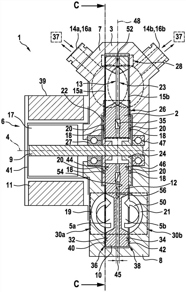
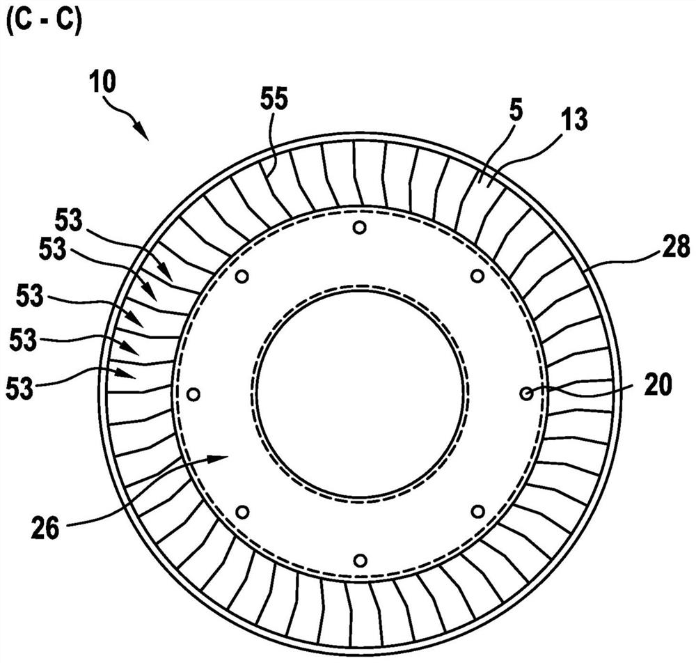
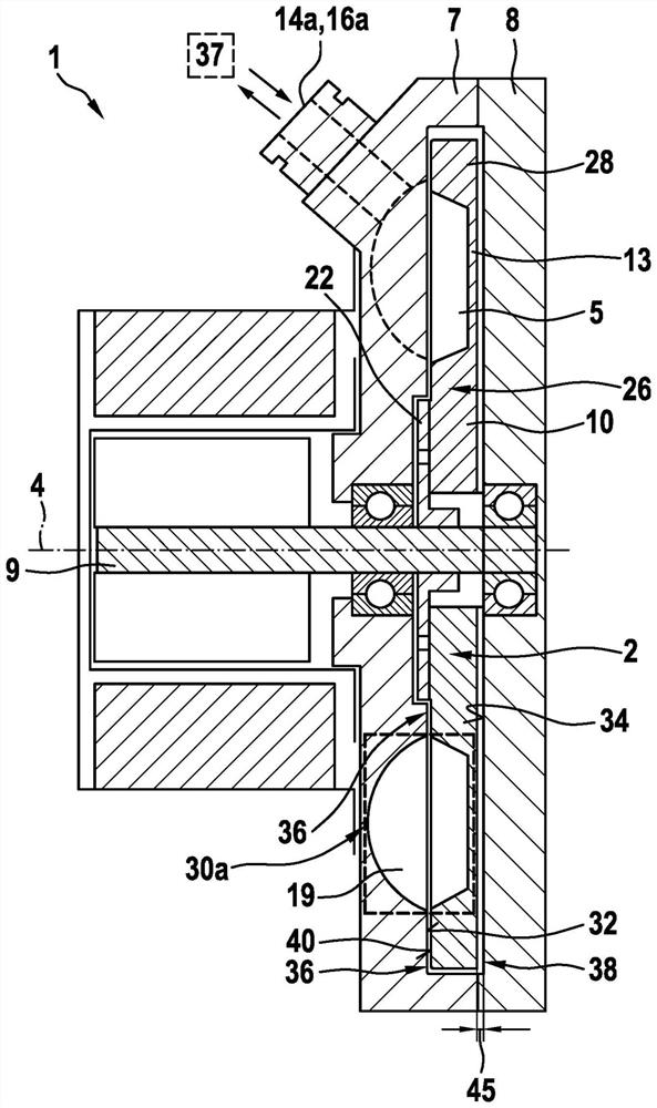
[0021] from according to figure 1 The illustration in FIG. 1 results in a schematic sectional view of a side channel compressor 1 according to the invention and a compressor wheel 2 according to the invention according to a first embodiment.

[0022] In this case, side channel compressor 1 is arranged in the anode circuit of fuel cell system 37 as a component, for example in addition to the ejector pump, and serves to convey and / or compress a gaseous medium, in particular hydrogen. In this case, the side channel compressor 1 has a housing 3 , with a compressor chamber 30 located in the housing 3 , which has at least one surrounding side channel 19 , 21 . Here, the compressor wheel 2 is located in the housing 3 , wherein the compressor wheel 2 is arranged rotatably about the axis of rotation 4 , and wherein the compressor wheel 2 has compression rings arranged on its circumference around the axis of rotation 4 . The delivery unit 5 in the area of ​​the machine room 30 . The d...


PUM


Abstract

The invention relates to a side-channel compressor (1) for a fuel cell system (37) for conveying and/or compressing a gaseous medium, in particular hydrogen, comprising a housing (3); a compressor chamber (30) which is situated in the housing (3) and which has at least one encircling side channel (19, 21); a compressor impeller (2) which is situated in the housing (3) and which is arranged so as to be rotatable about a rotational axis (4), wherein the compressor impeller (2) has conveying cells (5) arranged on the impeller circumference in the region of the compressor chamber (30), and the conveying cells (5) are delimited by a circumferential inner delimiting ring (26) on the side facing the rotational axis (4); and in each case at least one gas inlet opening (14) formed on the housing (3) and one gas outlet opening (16), which are fluidically connected together via the compressor chamber (30) and the at least one side channel (19, 21). The housing (3) has at least one respective end face (32, 34) radially to the rotational axis (4), each end face facing the compressor impeller (2), and at least one functionally relevant gap dimension (36, 38) is formed in the region of each gap surface. According to the invention, the compressor impeller (2) has at least one impeller shell (10, 12), said impeller shell having a lateral wall (13, 23) which runs radially to the rotational axis (4) and/or an outer delimiting ring (28) which runs parallel to the rotational axis, whereby a fluidic encapsulation of the conveying cells (5) and/or the side channel (19, 21) is produced in particular.

Description

technical field [0001] The invention relates to a side-channel compressor for conveying and / or compressing a gaseous medium, in particular hydrogen, for a fuel cell system, in particular intended for use in a vehicle with a fuel cell drive . Background technique [0002] In the field of vehicles, besides liquid fuels, gaseous fuels will also become more and more important in the future. Especially in vehicles with a fuel cell drive, the hydrogen flow must be controlled. In this case, the gas flow is no longer controlled discontinuously as in the case of liquid fuel injection, but the gaseous medium is taken from at least one high-pressure tank and directed via the inflow line of the medium-pressure line system to the injector unit. The injector unit directs the gas to the fuel cell via the connecting lines of the low-pressure line system. After the gaseous medium has flowed through the fuel cell, it is led back to the injector unit via a return line. In this case, a side...

Claims


Application Information

Patent Timeline
Patent Type & Authority Applications(China)
IPC IPC(8): F04D23/00F04D29/02F04D29/26F04D29/28
CPCF04D23/008F04D29/284F04D29/266F04D29/023F05D2300/43Y02E60/50
Inventor M·库尔茨
Owner ROBERT BOSCH GMBH
Why Eureka
Try Eureka