High-speed railway ballastless track cable-stayed bridge steel truss combined girder structure

A ballastless track and cable-stayed bridge steel technology, applied in bridges, bridge parts, bridge construction, etc., can solve the problems of poor structural performance, easy cracking, and low stiffness of the top surface of the steel bridge deck and the track base plate, and achieve the guarantee The effect of driving comfort, crack avoidance, and high structural rigidity

Active Publication Date: 2021-07-27
CHINA MAJOR BRIDGE ENERGINEERING
View PDF7 Cites 0 Cited by
  • Summary
  • Abstract
  • Description
  • Claims
  • Application Information

AI Technical Summary

Problems solved by technology

[0009] In view of the above defects, the technical problem to be solved by the present invention is to provide a high-speed railway ballastless track cable-stayed bridge combined with the main girder structure to solve the existing steel truss Beam or steel box girder ballastless track cable-stayed bridges have the problems of low rigidity, poor structural performance of the top surface of the steel bridge deck and track base plate, and easy cracking

Method used


Image

  • High-speed railway ballastless track cable-stayed bridge steel truss combined girder structure
  • High-speed railway ballastless track cable-stayed bridge steel truss combined girder structure
  • High-speed railway ballastless track cable-stayed bridge steel truss combined girder structure

Examples


specific Embodiment 1

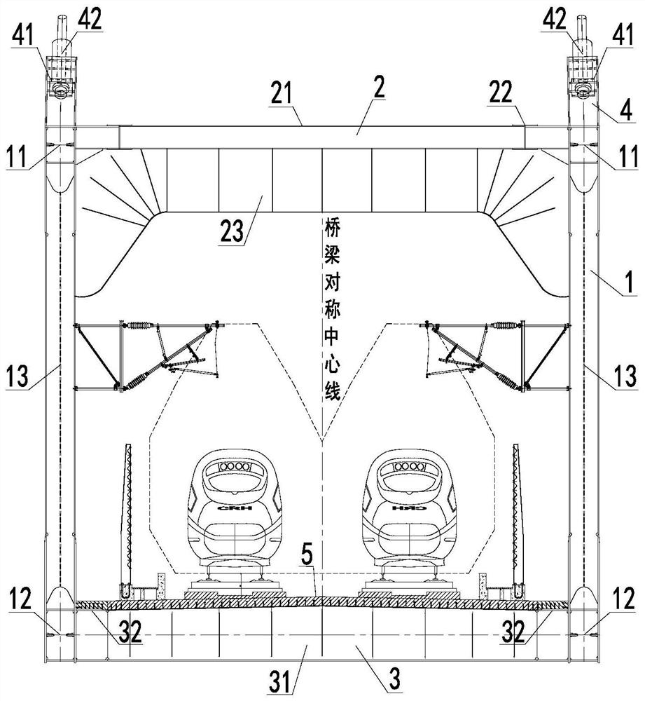
[0070] Such as figure 1 As shown, the high-speed railway ballastless track cable-stayed bridge combined main girder structure provided by the present invention includes a main truss 1 , a transverse connection system 2 , a combined bridge deck and a cable-stayed anchorage structure 4 .

[0071] The main truss 1 is arranged on both sides, and the transverse connection system 2 is arranged between the main trusses 1 and on the upper part of the first main truss; In the lower part, the concrete bridge deck 5 is arranged on the top surface of the steel beam 3 for laying the ballastless track slab. The stay cable anchoring structure 4 is arranged on the top surface of the main girder 1, and is used for anchoring the stay cables.

[0072] The main truss, transverse connection system, steel truss girder and cable-stayed anchorage structure form an internode structure, and one or two internodes form the overall section of the steel beam. During construction, the manufacture of the in...

specific Embodiment 2

[0074] This specific embodiment 2 is based on the specific embodiment 1, and further optimizes and improves the main girder and the transverse connecting system.

[0075] Such as Figure 4 As shown, the main truss 1 is arranged on both sides, including an upper chord 11, a lower chord 12 and a diagonal 13. The upper chord 11 and the lower chord 12 are arranged opposite to each other along the longitudinal bridge, and the upper chord 11 and the lower chord 12 are parallel. The diagonal web 13 is arranged between the upper chord 11 and the lower chord 12 , and the two ends of the diagonal web 13 are respectively welded between the upper chord 11 and the lower chord 12 . The upper chord 11, the lower chord 12 and the oblique web 13 are H-shaped cross-section rods or box-shaped cross-section rods, and the upper chord 11, lower chord 12 and diagonal web rods 13 form the triangular truss structure of the main truss 1, which improves the strength of the main truss 1. structural stif...

specific Embodiment 3

[0079] This specific embodiment 3 is based on the specific embodiment 2, and further optimizes and improves the steel beam and the concrete bridge deck.

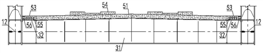
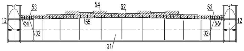
[0080] Such as figure 2 , image 3 , Image 6 , Figure 7 with Figure 8 As shown, the steel beam 3 includes a lower beam 31 and a longitudinal long section 32, the lower beam 31 is arranged on the inner side of the lower part of the lower chord 12, and a plurality of lower beams 31 are equidistantly distributed along the longitudinal bridge direction. The long longitudinal section 32 is arranged on the top surface of the lower beam 31 , and the left and right ends of the long longitudinal section 32 are respectively welded to the inner web of the lower chord 12 .

[0081] The concrete bridge deck 5 includes a precast concrete deck 51 and a ballastless track base plate 54. Before assembling each precast concrete bridge deck 51, it is required to ensure that the concrete precast deck must have sufficient beam storage tim...


PUM


Abstract

The invention discloses a high-speed railway ballastless track cable-stayed bridge steel truss combined girder structure which comprises main trusses and a transverse linkage system, wherein the main trusses are arranged on the two sides, and the transverse linkage system is arranged between the main trusses and arranged on the upper portions of the main trusses; a combined bridge deck comprises a steel cross beam and a concrete bridge deck slab, the steel cross beam is fixed to the lower portion of the main truss, and the concrete bridge deck slab is arranged on the top face of the steel cross beam and used for laying ballastless track slabs; and a stay cable anchoring structure is arranged on the top surface of the main truss structure. The steel truss girder and concrete bridge deck slab combined main girder structure form is adopted, the structural rigidity is large, the smoothness of a track structure can be improved, and the safety and driving comfort of a high-speed train are guaranteed; the combination performance of the concrete bridge deck and the railway track plate base plate is good, the structural durability is good, and the maintenance work is greatly reduced; meanwhile, the bridge deck slab is of a concrete structure, the steel consumption of the main beam is reduced, and economic benefits are good.

Description

technical field [0001] The invention relates to the technical field of bridge girders, in particular to a steel truss combined main girder structure of a cable-stayed bridge with ballastless track for high-speed railways. Background technique [0002] Ballastless track refers to the track structure that uses concrete, asphalt mixture and other integral foundations to replace the loose-grained gravel track bed, also known as slagless track, which is an advanced track technology in the world today. The ballastless track adopts the concrete or asphalt track bed with better stability instead of the ballast track bed to transmit the dynamic and static loads during driving. [0003] Ballastless track has high requirements for construction and design. The control of track surface irregularity caused by beam end angle and bridge deck deformation is the key technical requirement for laying ballastless track. "Code for Design of Railway Bridges and Culverts" stipulates that the vert...

Claims


Application Information

Patent Timeline
Patent Type & Authority Applications(China)
IPC IPC(8): E01D12/00E01D19/14
CPCE01D12/00E01D19/14
Inventor 肖海珠李松林别业山张建强唐超舒思利黄赟黄玲
Owner CHINA MAJOR BRIDGE ENERGINEERING
Why Eureka
Try Eureka