
Speed reducer installing and positioning device facilitating shaft alignment

A technology for installation, positioning and reducer, which is applied in metal processing, metal processing equipment, manufacturing tools, etc., and can solve problems such as time-consuming, waste of manpower and material resources, and difficulty in aligning axes

Inactive Publication Date: 2021-07-30
杭州阅希电梯销售有限公司
View PDF0 Cites 1 Cited by
  • Summary
  • Abstract
  • Description
  • Claims
  • Application Information

AI Technical Summary

Problems solved by technology

[0005] Aiming at the deficiencies of the prior art, the present invention provides a gear reducer installation and positioning device that is convenient for shaft alignment, which has the automatic and precise docking of the shaft end of the reducer and the shaft end of the installation equipment, and can easily contact the docking between the two The advantage of easy maintenance solves the problem that it is difficult to align the shaft when installing the reducer. The operator needs to adjust it slowly. There are errors in manual operation and it is difficult to accurately dock, so it takes a lot of time in the adjustment process. The problem of wasting manpower and material resources

Method used


Image

  • Speed reducer installing and positioning device facilitating shaft alignment
  • Speed reducer installing and positioning device facilitating shaft alignment
  • Speed reducer installing and positioning device facilitating shaft alignment

Examples


Embodiment Construction

[0023] The following will clearly and completely describe the technical solutions in the embodiments of the present invention with reference to the accompanying drawings in the embodiments of the present invention. Obviously, the described embodiments are only some, not all, embodiments of the present invention. Based on the embodiments of the present invention, all other embodiments obtained by persons of ordinary skill in the art without making creative efforts belong to the protection scope of the present invention.

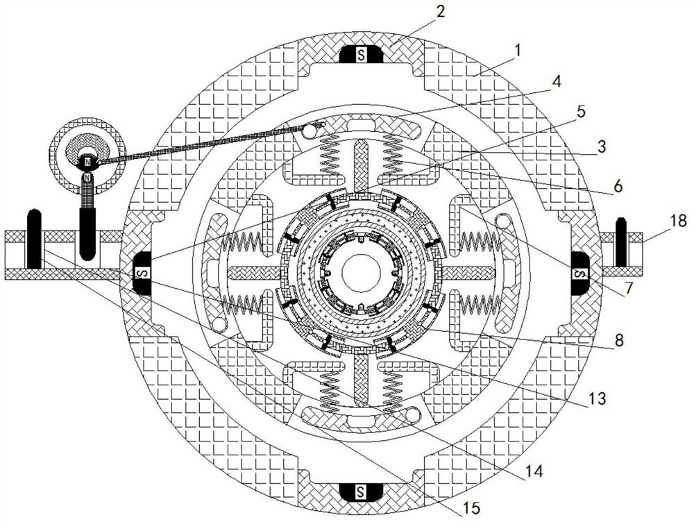
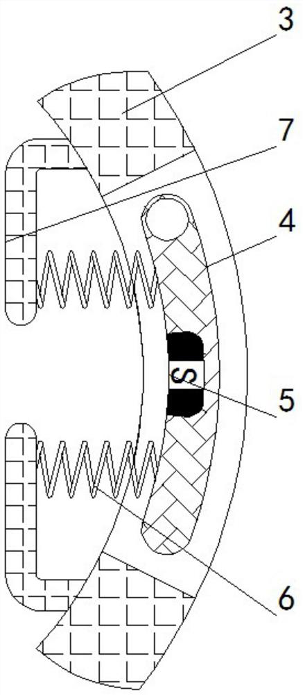
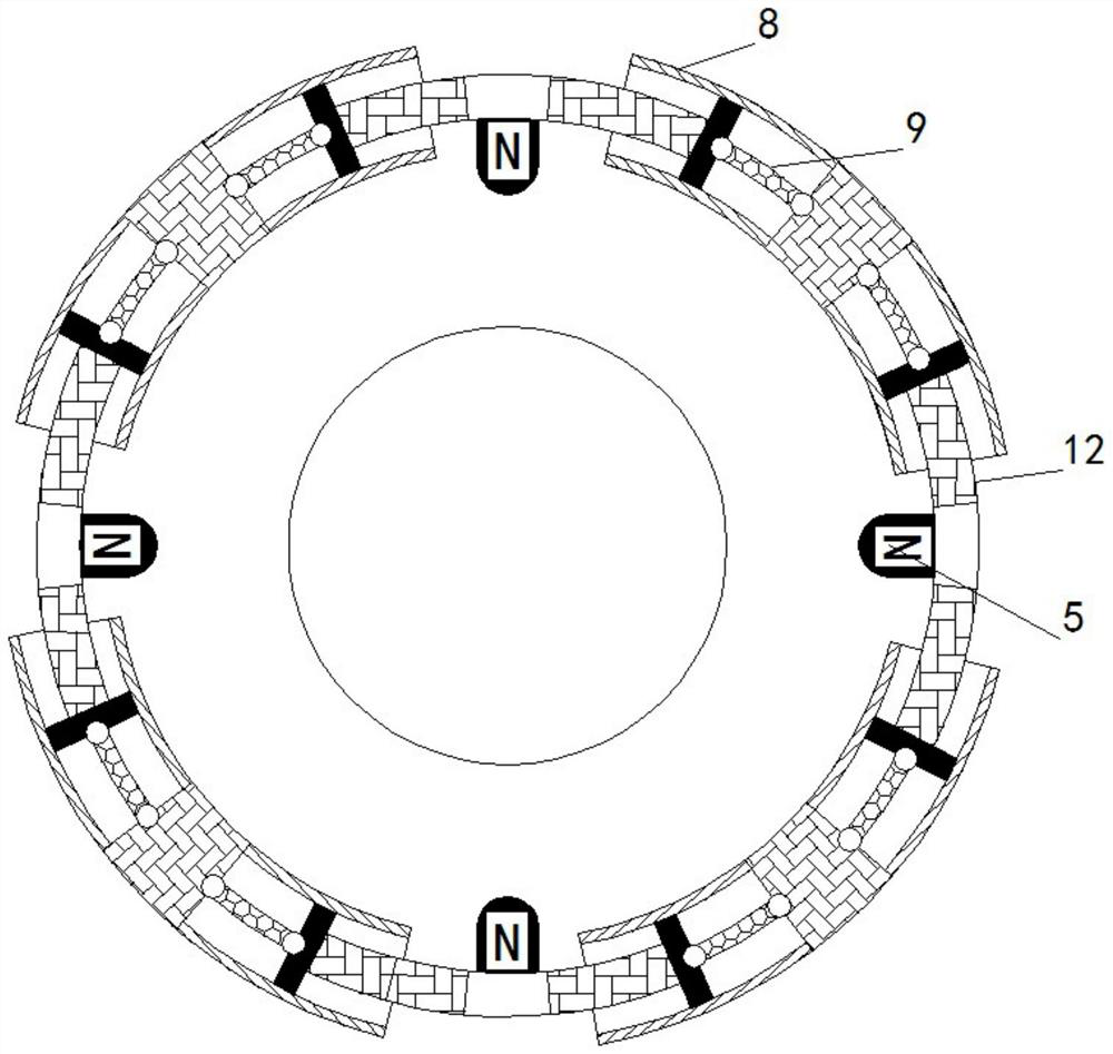
[0024] see Figure 1-4 , a gear reducer that facilitates the installation and positioning of the shaft, including a fixed disc 1, a card seat 2 is provided on the inner wall of the fixed disc 1, a rotating shaft 3 is fixedly installed inside the fixed disc 1, and a rotating shaft 3 is movably installed on the outer wall of the fixed disc 1 The rotating plate 4 and the inside of the deck 2 are fixedly equipped with a magnet 5. There are two magnets 5. The magne...


PUM


Abstract

The invention relates to the technical field of speed reducer installing and positioning, and discloses a speed reducer installing and positioning device facilitating shaft alignment. The speed reducer installing and positioning device comprises a fixing plate, a clamping base is arranged on the inner wall of the fixing plate, a rotating shaft is fixedly installed in the fixing plate, and a rotating plate is movably installed on the outer wall of the rotating shaft. a magnet is fixedly installed inside a clamping base, and the inner wall of the rotating plate is fixedly connected to a spring. By slightly rotating the rotating shaft, when the magnet in a circular ring is aligned with the magnet in the clamping base, when the magnet is not aligned with the magnet in the clamping base, the attraction force between the two magnets can be blocked under the action of a baffle, after the rotating shaft is aligned with the fixing plate, under the action of the magnets, the circular ring expands towards the outer side, an air bag pushes the circular ring on the outer side to expand, an ejector rod ejects the rotating plate, the rotating plate enters the clamping base, the rotating shaft and the fixing plate move synchronously, and the effect of precise butt joint of the rotating shaft of the speed reducer is achieved.

Description

technical field [0001] The invention relates to the technical field of reducer installation and positioning, in particular to a reducer installation and positioning device for convenient shaft alignment. Background technique [0002] A reducer is an independent component consisting of a gear transmission, a worm gear, and a gear-turbine drive enclosed in a rigid shell. It is often used as a reduction transmission device between the prime mover and the working machine. It plays the role of matching speed and transmitting torque between prime mover and working machine or actuator. [0003] When installing the reducer, it is necessary to accurately dock the shaft end of the reducer with the shaft end on the installation equipment, but at present, when installing the reducer, it is difficult to align the shaft, and the operator needs to adjust it slowly, manually There are errors in the operation, and it is difficult to accurately dock, so it takes a lot of time in the adjustme...

Claims


Application Information

Patent Timeline
Patent Type & Authority Applications(China)
IPC IPC(8): B23P19/10
CPCB23P19/10
Inventor 陈明位张楚玲
Owner 杭州阅希电梯销售有限公司
Learn More