
A clamping device and clamping method for large thin-walled frame-type precision casting parts

A clamping device and frame-type technology, applied in positioning devices, metal processing machinery parts, clamping, etc., can solve problems such as difficulty in ensuring the coordination relationship of parts, affecting appearance and performance, and stress concentration of parts, so as to reduce processing vibration, The effect of reducing the time occupied by the machine tool and reducing the vibration

Active Publication Date: 2022-05-10
CHENGDU AIRCRAFT INDUSTRY GROUP
View PDF12 Cites 0 Cited by
  • Summary
  • Abstract
  • Description
  • Claims
  • Application Information

AI Technical Summary

Problems solved by technology

[0006] Riveting assembly will cause stress concentration of parts, affecting the overall appearance and performance;
[0007] The assembly accuracy is low, and the coordination relationship of parts is difficult to guarantee
[0008] Therefore, the integral molding and processing of large thin-walled frame-type precision castings is an effective measure to ensure the processing quality of parts. However, the integrally formed large-scale thin-walled frame-type precision castings have processing bottlenecks such as poor part rigidity and large deformation, and there is an urgent need for stable and reliable Advanced clamping device and method to improve the stability of the processing process of the weak rigid structure of the part, so as to ensure the processing quality of the part

Method used


Image

  • A clamping device and clamping method for large thin-walled frame-type precision casting parts
  • A clamping device and clamping method for large thin-walled frame-type precision casting parts
  • A clamping device and clamping method for large thin-walled frame-type precision casting parts

Examples


Embodiment 1

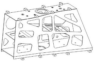
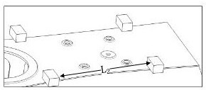
[0068] A large thin-walled frame type precision casting parts clamping device, the parts 7 are placed on the tooling backing plate 6, such as figure 2 As shown, the upper and lower surfaces of the part 7 are respectively provided with double rows of semi-suspended bosses 1 along the length of the parallel sides; Figure 6 As shown, the open end area of ​​the part 7 is provided with an open end area pressing device 2, and the upper surface of the part 7 is provided with a top surface boss pressing device 4; the bottom of the part 7 is provided with There is a pressing device 3 for positioning bosses on the bottom surface; a pressing device 5 in the middle web hole area is provided in the middle of the part 7 for double-sided pressing of the web of the part 7 .

[0069] The present invention is provided with upper and lower double-sided, left-right double-sided bosses 1, which can ensure that there are pressing connection devices on the upper and lower surfaces of the casting, ...

Embodiment 2

[0071] This embodiment is optimized on the basis of embodiment 1, such as Figure 7 , Figure 8 As shown, the open-end area pressing device 2 includes a mounting base and an upper pressing device and a lower pressing device arranged on the mounting base, and the upper pressing device and the lower pressing device are fixedly clamped Part 7; also includes a support 8 and a bracket 11, the top of the support 11 is connected to the mounting seat, and the bottom is connected to the support 8 through a bolt 10, and the support 8 is detachably connected to the tooling backing plate 6.

[0072] Further, as Figure 7 , Figure 8 As shown, the upper end pressing device includes a pressing plate 13, a stud 16, a guide screw 12, and a nut 14, and the stud 16 and the guide screw 12 are arranged in parallel on the mounting seat, and the pressing plate 13 is connected with the stud 16 and the guide respectively. The screw 12 is slidingly connected, and the stud 16 passes through the pres...

Embodiment 3

[0076] This embodiment is optimized on the basis of embodiment 1 or 2, as Figure 14-Figure 18 As shown, the pressing device 5 in the middle web hole area includes a pillar 27, an adjusting nut 26, a washer 25, and a circular pressure plate 24. The pillar 27 is arranged inside the part 7, and the bottom of the pillar 27 passes through the part 7 And be connected with tool backing plate 6, and the top passes through the web of part 7 upwards and is connected with circular pressure plate 24, and screw 9 passes through circular pressure plate 24 and is threaded with the top of pillar 27; A washer 25 and an adjusting nut 26 are sequentially arranged on the pillar 27 from top to bottom. The washer 25 is slidably installed on the pillar 27 , and the adjusting nut 26 is screwed to the pillar 27 .

[0077] There are large-diameter holes in the upper and lower middle areas of the casting, which belong to the weakest rigidity of the entire casting. The present invention is suitable for ...


PUM


Abstract

The invention discloses a clamping device and a clamping method for a large thin-walled frame type precision casting part. The upper and lower surfaces of the part are respectively provided with double rows of semi-suspended bosses along the length of parallel sides; the ends of the part are open The open area is equipped with a pressing device for the open area of ​​the end. The upper surface and the lower surface of the part are respectively provided with a pressing device for the top surface boss and a pressing device for the bottom positioning boss, and the middle part is provided with the middle web hole area. Compression device for double-sided compression of the web of the part. The clamping device can effectively enhance the rigidity of precision casting parts, reduce the problems caused by the lack of rigidity of the parts during the processing, such as springing and vibration, and ensure the stability and reliability of the processing process; the clamping method is suitable for large thin The wall frame type precision casting parts can improve the stability of the weak rigid structure of the parts in the processing process. It is a stable, reliable and flexible clamping method with good practicability.

Description

technical field [0001] The invention belongs to the technical field of clamping casting parts, and in particular relates to a clamping device and a clamping method for large thin-walled frame-type precision casting parts. Background technique [0002] While making full use of many excellent properties of metal materials, precision castings can realize the precise molding of large thin-walled complex structures, effectively improve material utilization, reduce the amount of machining, thereby reducing production costs and shortening production cycles. With the development of precision casting technology in recent years, the manufacture of large, thin-walled, complex, integral and precision castings has become the development trend of foreign aerospace vehicle precision casting structural parts manufacturing technology. Such castings have good overall structure and high reliability. , light weight and low processing cost, it is more and more widely used in the aerospace field....

Claims


Application Information

Patent Timeline
Patent Type & Authority Patents(China)
IPC IPC(8): B23Q3/06
CPCB23Q3/062
Inventor 陈清良刘元吉姜振喜匡勇勾江洋
Owner CHENGDU AIRCRAFT INDUSTRY GROUP
Learn More