
Abrasive wire feeding and discharging mechanism

A kind of abrasive wire and filament technology, which is used in thin material handling, transportation of filamentous materials, transportation and packaging, etc., can solve problems such as heavy workload, inability to ensure consistent feed speed, and low work efficiency.

Active Publication Date: 2021-07-30
ZHEJIANG MOPPER ENVIRONMENTAL TECH CO LTD
View PDF13 Cites 0 Cited by
  • Summary
  • Abstract
  • Description
  • Claims
  • Application Information

AI Technical Summary

Problems solved by technology

If the abrasive wire is laid manually on the steel belt in the same direction, the workload will be large and the work efficiency will be low
If only the belt is used to carry the abrasive wire to convey the abrasive wire, it cannot guarantee that the feeding speed of the abrasive wire falling onto the belt is consistent with the feeding speed of the belt

Method used


Image

  • Abrasive wire feeding and discharging mechanism
  • Abrasive wire feeding and discharging mechanism
  • Abrasive wire feeding and discharging mechanism

Examples


Embodiment Construction

[0045] In order to further understand the content of the present invention, the present invention will be described in detail in conjunction with the accompanying drawings and specific embodiments.

[0046] In describing the present invention, it is to be understood that the terms "center", "upper", "lower", "front", "rear", "left", "right", "vertical", "horizontal", The orientations or positional relationships indicated by "top", "bottom", "inner", "outer", etc. are based on the orientations or positional relationships shown in the drawings, and are only for the convenience of describing the present invention and simplifying the description, rather than indicating or implying the It should not be construed as limiting the invention that a device or element must have a particular orientation, be constructed, and operate in a particular orientation.

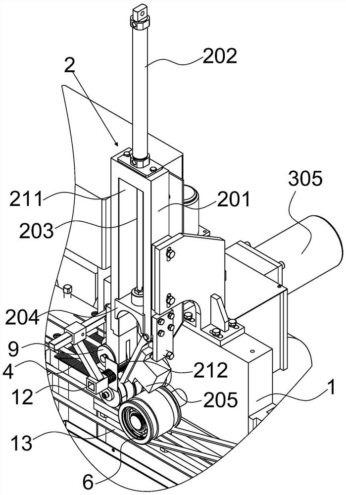
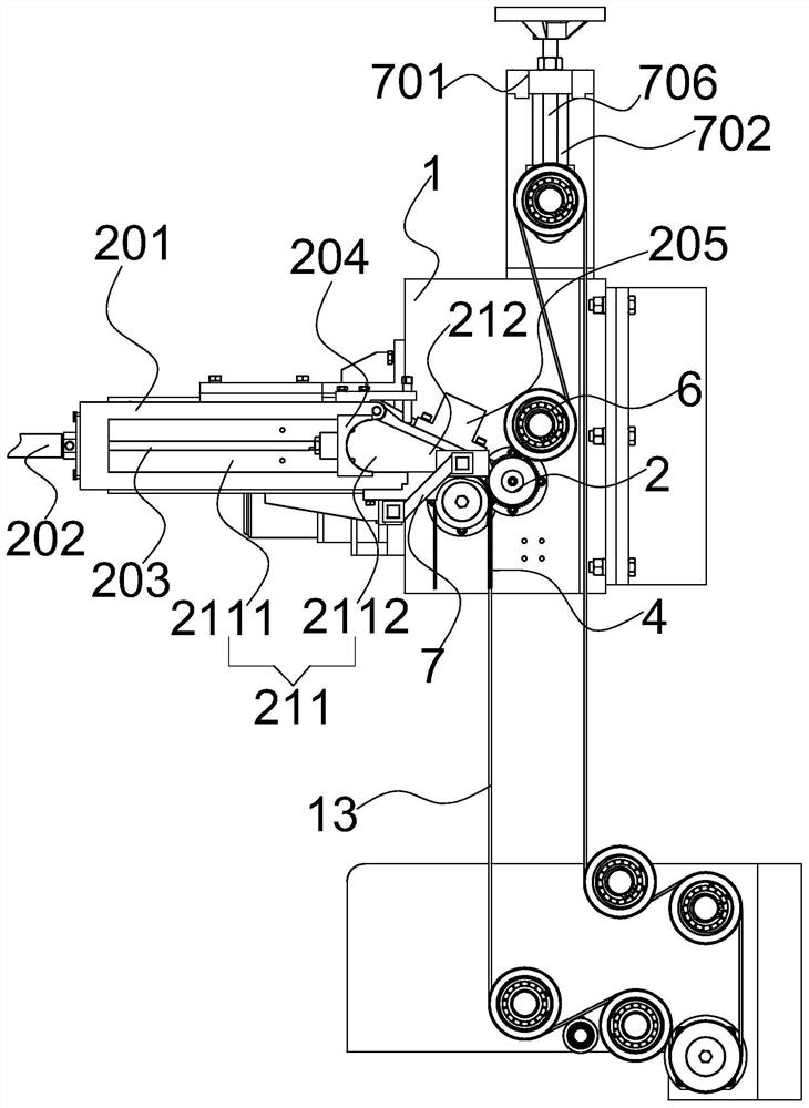
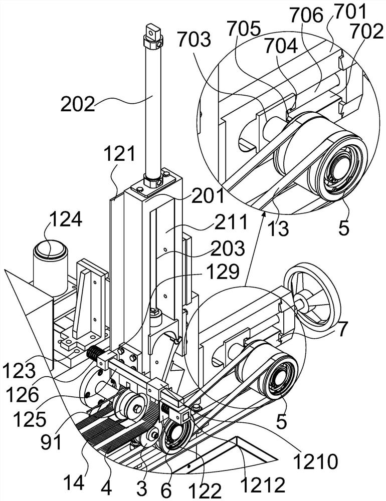
[0047] see Figure 1-19 In this embodiment, an abrasive wire feeding and discharging mechanism is proposed, which includes a ba...


PUM


Abstract

The invention discloses an abrasive wire feeding and discharging mechanism which comprises a base, wherein an abrasive wire discharging assembly and an abrasive wire feeding assembly are arranged on the base. The abrasive wire discharging assembly comprises a material storage part connected with the base, a material storage groove and a discharging opening are formed in the material storage part, and the discharging opening communicates with the material storage groove; the abrasive wire feeding assembly comprises a wire shifting wheel set located at the discharging port; a material wire shifting wheel set comprises a driving shaft, a material wire shifting wheel arranged on the driving shaft in a sleeving mode and two belt wheels; the driving shaft is in relative rotating connection with the base; the material wire shifting wheel and the driving shaft are fixedly connected in the circumferential direction and rotate synchronously so as to bear the abrasive wire in the material storage groove and shift the abrasive wire to move forwards; the two belt wheels are arranged on two sides of the material wire shifting wheel respectively and connected with the driving shaft in a circumferential rotating mode; a belt is supported on the belt pulley in a penetrating mode and used for bearing the abrasive wire shifted by the wire shifting wheel and moves forwards along with the abrasive wire through friction force, synchronous conveying of the belt and the abrasive wire is achieved, and the problem that the feeding speed of the abrasive wire is inconsistent with the conveying speed of the belt is avoided.

Description

technical field [0001] The invention relates to the technical field of feeding equipment, more specifically, to an abrasive wire feeding and discharging mechanism. Background technique [0002] Flat steel is used in many fields, and it is generally a hot-rolled steel plate. It is inevitable to produce stains and rust on the surface during production. Therefore, before its use, it is necessary to treat the stains and rust on its surface to meet the production requirements. Traditionally, the treatment method for the flat steel strip generally adopts a chemical treatment method, and an acidic liquid is used to remove the rust and some pollutants on the surface of the flat steel strip. However, if the flat steel strip is treated with an acidic liquid, more acidic waste liquid will be produced in the end, which will pollute the environment and is not environmentally friendly. [0003] In order to meet the needs of the market, there is currently a device on the market that uses...

Claims


Application Information

Patent Timeline
IPC IPC(8): B65H51/06B65H57/14B65H51/14
CPCB65H51/06B65H57/14B65H51/14B65H2701/31
Inventor 傅如学张成祥刘春晓
Owner ZHEJIANG MOPPER ENVIRONMENTAL TECH CO LTD
Learn More