

Ultrasonic tin plating device and tin plating method
A tinning device and ultrasonic technology, applied in hot-dip plating process, coating, metal material coating process, etc., can solve the problems of environmental protection, environmental protection restrictions, pollution and other problems in the large-scale use of flux, and meet the requirements of large-scale production Demand, the effect of solving environmental problems
- Summary
- Abstract
- Description
- Claims
- Application Information
AI Technical Summary
Problems solved by technology
Method used
Image

Examples
Embodiment
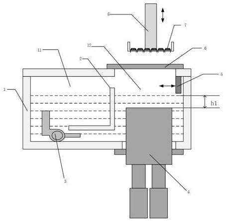
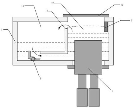
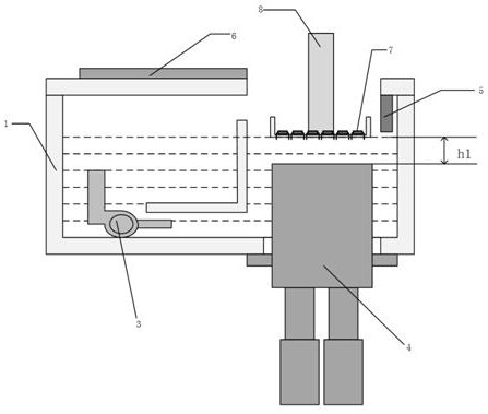
[0033] Please refer to figure 1 , the present embodiment provides an ultrasonic tinning device, including: a closed tin tank 1, an ultrasonic vibration device 4 and a tin pump 3; the closed tin tank 1 includes a cavity and an openable door 6, and the cavity has a first Chamber 11, second chamber 12, an opening is provided above the second chamber 12, an openable door 6 is arranged on the opening and can open or close the opening, the first chamber 11 communicates with the second chamber 12, and the tin pump 3 is used to pump tin liquid from the first chamber 11 to the second chamber 12, and the ultrasonic vibration device 4 is arranged in the cavity and used to transmit ultrasonic energy to the tin liquid in the second chamber 12.
[0034] Wherein, it may be selected that the length and width of the ultrasonic tinning area of the ultrasonic vibration device 4 are greater than 50 mm×50 mm. In this embodiment, the length and width of the ultrasonic tinning area of the ultra...
PUM
 Abstract
Description
Claims
Application Information