
Civil engineering shielding engineering wall member

A wall and component technology, applied in the field of civil engineering shielding wall components, can solve the problems of increasing the cost of walls, increasing the difficulty and cost of wall construction, and being unsuitable for civil engineering applications.

Pending Publication Date: 2021-07-30
SHANGHAI ZHAIXI ENG TECH CO LTD
View PDF0 Cites 0 Cited by
  • Summary
  • Abstract
  • Description
  • Claims
  • Application Information

AI Technical Summary

Problems solved by technology

Obviously, the above-mentioned methods all need to increase the specifications of the wall panels, which will increase the cost of the wall, and will also increase the difficulty and cost of wall construction
[0004] In addition, most of the existing prefabricated wall panels and floor panels are split structures, which need to be assembled at the construction site, which has poor integrity, low connection strength, and increases the difficulty of construction
[0005] In addition, for high-risk places such as mudslides, landslides, and large-volume material collapses, the retaining wall will also be damaged, resulting in slippage and overturning accidents.
However, the current retaining wall does not have any accident warning and alarm functions.
The equipment with forecasting and alarm functions are all high-tech products, the cost is very high, and they are not suitable for application in conventional civil engineering

Method used


Image

  • Civil engineering shielding engineering wall member
  • Civil engineering shielding engineering wall member
  • Civil engineering shielding engineering wall member

Examples


Embodiment Construction

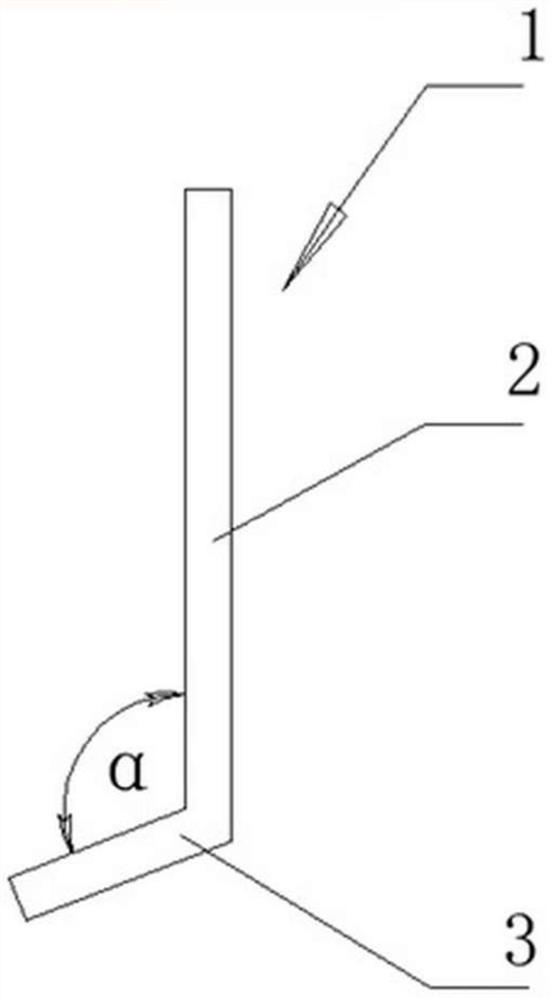
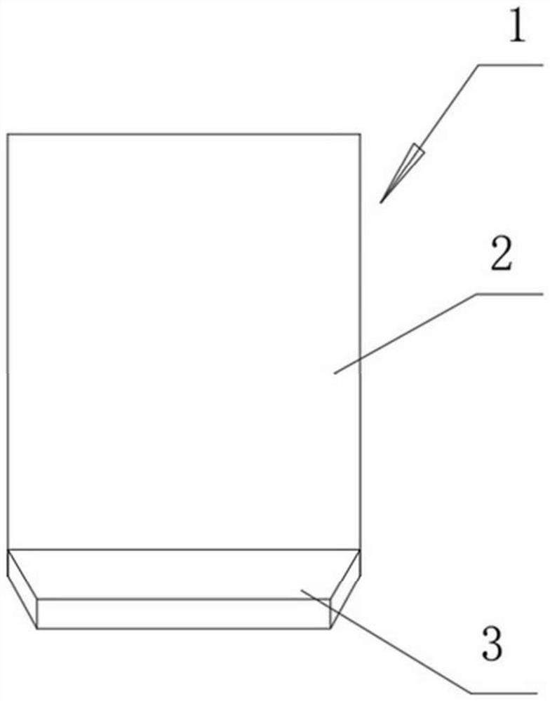
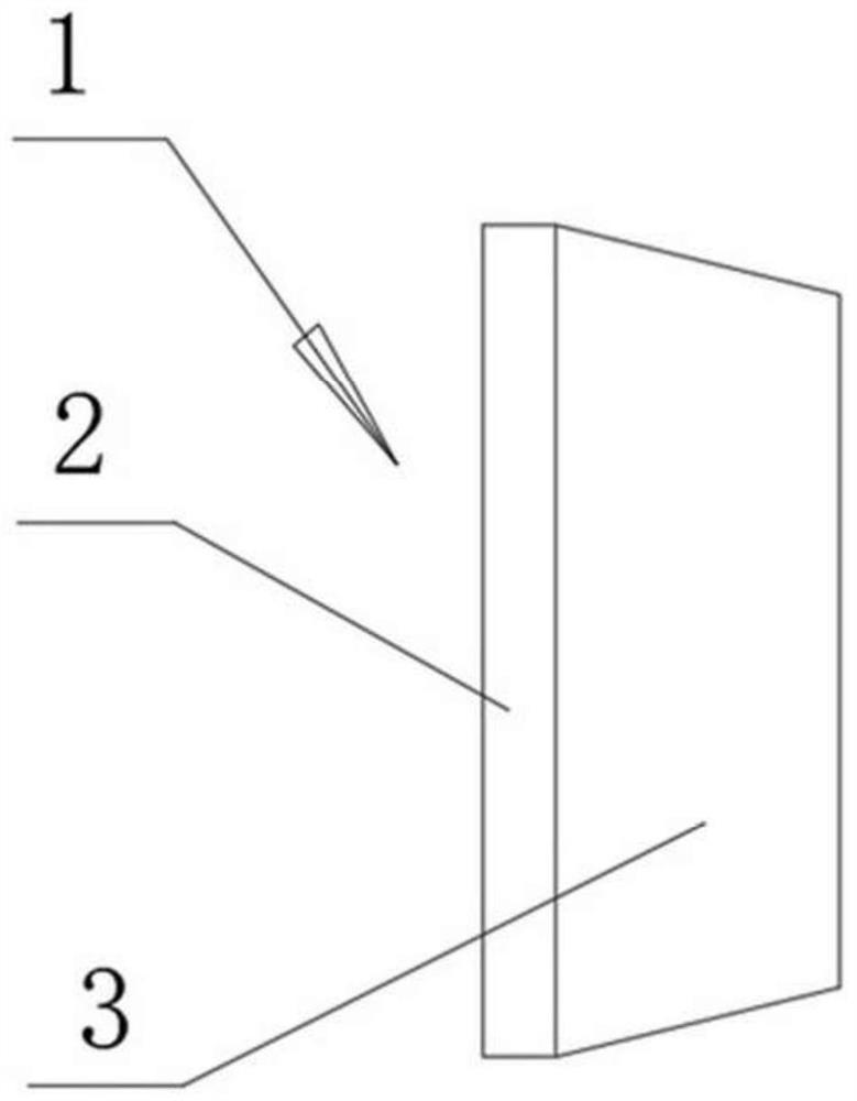
[0051] The first embodiment: In order to improve the performance of the existing retaining wall, a civil shielding engineering wall component is provided. Such as figure 1 , figure 2 , image 3 As shown, the main body of this wall component 1 is also an upright wallboard 2, and a bottom plate 3 extending to one side of the wallboard is provided below the wallboard. The improvement is: the wall board and the bottom board are fixedly connected together, preferably reinforced cement concrete prefabricated parts. The included angle between the wall board and the bottom board is not a right angle, but an obtuse angle greater than 90 degrees. According to a large number of experiments and calculations, the obtuse angle should be between 100-110 degrees, preferably 105 degrees.

[0052] Figure 4 The installation structure of the previous wall panel is introduced. The angle between the wall panel and the bottom plate in the figure is 90 degrees. The installation requires a larg...


PUM


Abstract

The invention relates to the field of constructional engineering, in particular to a civil engineering shielding engineering wall member (1) which comprises a vertical wallboard (2); a bottom plate (3) is arranged below the wallboard (2); the civil engineering shielding engineering wall member is characterized in that the wallboard (2) and the bottom plate (3) are fixedly connected with form an integral member; and an included angle alpha between the wallboard (2) and the bottom plate (3) is an obtuse angle. The civil engineering shielding engineering wall member has the beneficial effects that a friction force between the bottom plate and a foundation and an anti-overturning torque of a wall body are greatly increased, and the anti-sliding and anti-overturning performance of the wall body is remarkably enhanced; the burial depth of the outer side of the wall body is reduced, the available height of the wall body is increased, the self weight is reduced, and the raw material cost is greatly reduced; and the wall body and the bottom plate are integrally prefabricated members, so that batch production is facilitated, manufacturing cost is low, precision is high, installation is convenient, the construction period is short, and environmental influence is small. The civil engineering shielding engineering wall member is particularly suitable for civil construction under the conditions of steep mountain slopes and the like, is widely applied to projects such as road, mine, terraced field and village construction, river desert control and the like, and has a very considerable market prospect.

Description

technical field [0001] The invention relates to a construction equipment, namely a wall component of a civil shielding project. Background technique [0002] The civil shielding engineering wall, commonly known as the retaining wall, is a wall used to block and fix slopes or mountains, as well as large amounts of earth and stone in construction engineering, to prevent them from sliding. In projects such as railways, highways, mines, water conservancy, and urban transportation, especially in environmental conditions such as steep mountains and slopes, this kind of retaining wall is required for block division. Retaining walls are also used in projects such as terraced field construction in mountainous areas, village construction, and desert control. The structure of the existing retaining wall mainly includes an upright wall panel and a bottom plate below, which are mostly made of reinforced concrete and other materials, and are made by cast-in-situ or prefabricated methods....

Claims


Application Information

Patent Timeline
IPC IPC(8): E02D29/02G08B21/18
CPCE02D29/0266G08B21/187
Inventor 丛峰松斎喜重信
Owner SHANGHAI ZHAIXI ENG TECH CO LTD
Learn More